TAGGED: -Force-calculation, mesh
-
-
March 3, 2024 at 1:51 pm
Davide Givoia
SubscriberHi there, I sincerely apologize if i did something wrong in inserting this post but it's my first time.
I recently started using Ansys Workbench for my university studies with a simple tests obtaining questionable results. I started by replicating a uniaxial compression test of a cylindrical specimen (6mm high by 12mm diameter) which is crushed between two 1mm plates. Knowing E=50MPa, the area of ​​the specimen, the crushing and the initial height, I was able to calculate the constraint reaction that I would have to measure in the lower constrained plate.
Having clearly understood that the result (measured with a probe) would give variable results with the density of the mesh, I did more tests by increasing the latter. However, what happened is that as the mesh thickened the measured force grew until it stabilized at a value of 1388N against the target 942N, when instead I would have expected the opposite, as the mesh increased I should have approached the "real" value and not the opposite.
Thank anyone who can help me, obviously i will provide all the test setup. Davide -
March 3, 2024 at 2:32 pm
peteroznewman
SubscriberHi Davide,
Some information is missing from your description. What are the boundary conditions? It sounds like there are 3 bodies, two 1 mm plates and the 6 mm thick cylinder. Is the bottom face of the bottom plate a Fixed Support? How did you apply the displacement to the top plate and how much displacement did you apply?
Did you use Contact between the cylinder and the plates? What type of Contact?
What material properties did you define for the cylinder besides the Young's Modulus (E)?
Please show a screen shot of the Analysis Settings.
Please show a screen shot of the Mesh on the Cylinder.
-
March 3, 2024 at 3:40 pm
Davide Givoia
SubscriberThanks for the quick response! In order:
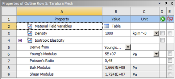
1- The material property was defined as follows:
Â
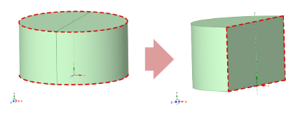
2- The geometry consists of a cylinder (having the dimensions mentioned above) divided into two parts joined by a "share topology" enclosed between 2 plates. This subdivision of the cylinder was done to simplify the meshing process conducted with the "edge sizing" command. The "edges" used in the meshing process are dashed red.
Â
2- The contacts between the plates and the cylinder were modeled considering friction on both sides:Â
Â
As you can see the cylinder is made up of two semi-cylinder (joined with "share topology") this was done to be able to better discretize the mesh using the "edge sizing"<"number of division .." command.
3- For the mesh I tried two "different" approaches (probably identical at this point) :
   1- Only using "edge sizing" on the cilinder and let the program mesh the plate without information:
   2- The second approach was the one that uses the "contact sizing" command relying on the respective "contact region"
4- As regards the analysis settings, the only things I worked on are the end time step of 6 seconds and the time step that I set equal to that of applying the load which goes from 0 to 6 seconds with a step of 0.1
5- Finally I fitted the lower part of the lower plate. with a "fixed support" and applied a "remote diplacement" to the upper surface of the top plate to which I applied the displacement history
6- The constraint reaction (searched force) was extracted with the "probe" command as show under:
I hope this can give you some more clues as to what the problem is, thanking you in advance I greet you and thank you! Davide
-
- The topic ‘Simple compression test on cilindrical specimen PROBLEM’ is closed to new replies.
-
2337
-
925
-
599
-
591
-
527
© 2025 Copyright ANSYS, Inc. All rights reserved.