Ansys Assistant will be unavailable on the Learning Forum starting January 30. An upgraded version is coming soon. We apologize for any inconvenience and appreciate your patience. Stay tuned for updates.
General Mechanical

General Mechanical

Topics related to Mechanical Enterprise, Motion, Additive Print and more.

SIFs along growing crack tip

    • langrin2
      Subscriber

      Hello


      I am currently trying to read out the SIFs along a growing crack tip.
      I am working in a static structural analysis using a pre-meshed crack and SMART crack growth.
      If I play the SIFS (K1) animation of the fracture tool, I can see that the SIF at the start is around 40 and at the end of the cycle around 6750. But if I have a look at the report, it just shows me the SIFs along the crack tip at the end of the cycle.
      Is there a way to read out the SIFs along the growing crack?


      Regards

    • David Weed
      Ansys Employee

      Hi,


      It sounds like you're performing fatigue crack growth. If so, then you'll have multiple substeps specified to calculate multiple crack extension increments. To retrieve the SIFS for each substep, under the details of the SIF result, specify Set Number, for a given substep, and re-evalute the result:


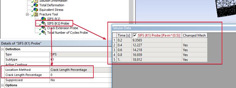
      Alternatively, you could also use the SIF probe and see the SIF result for each substep at a particular node along the crack front (using Crack Length Percentage; 0% is at first node in the front and 100% is last, 50% is in the middle, etc.):


      You could also make an APDL script, using the *get command and *do loop, to retrieve the SIF values at each substep and output them in a structured text file.


    • langrin2
      Subscriber

      Thank you very much for your answer, this helped a lot!


      Just one further question:
      Is it possible to get the SIFS (K1) Probe along a different path?


      I managed to read out the SIFS along the crack tip at position (1), is it possible to do the same thing at position (2)?


      And furthermore, would that it also be possible for the crack extension probe to be at different positions?


      Thank you and best regards

    • Sandeep Medikonda
      Ansys Employee

      Apparently CEINTF was used manually, possibly to connect reinforcing to the concrete.  To create constraint equations the nodes of the reinforcing are selected and the elements of the concrete.  The message implies nodes of the concrete are still selected.  That won't hurt anything in itself, but indicates a possible input error.

Viewing 3 reply threads
  • The topic ‘SIFs along growing crack tip’ is closed to new replies.
[bingo_chatbox]