TAGGED: vector-principal-stress, von-mises-stress
-
-
December 14, 2021 at 12:34 pm
Rameez_ul_Haq
SubscriberPlease observe the loading condition below, for a metal body made out of default SOLID elements in ANSYS. There is a stiffener on the top face (since theoretically, stiffeners decreases the total deformation as it stiffens the structure).
December 14, 2021 at 4:49 pmSaumadeep Choudhury
Forum Moderator
Yes, it is correct that the stresses/loads flow from the application region to the supports taking the shortest route. That is what happens here, hence the plate develops stress. As the load is applied, the plate deforms and hence the stresses are induced.
Now since the stiffener is attached to the upper surface of the plate, as the plate deforms due to load, the stiffener also deforms. Due to the deformation-induced on the stiffener bar, stresses develop on it.
Please refer to Stress and Strain (ansys.com)
Regards, Saumadeep
Ansys Help
Ansys Learning Forum (Rules & Guidelines)
December 14, 2021 at 5:50 pmRameez_ul_Haq
Subscriber,well thankyou for your anwer. But we don't see the load taking the shortest route in my example. I mean the load literally travels onto the stiffener and comes back down (and you explained the reason behind it). So does that mean this statement, "stresses/loads flow from the application region to the supports taking the shortest route" is not a generic statement but is dependent upon some things, like geometry, etc?
Plus, can we assume the stiffener to be an integral part of the main structure (like plate in this example) itself? I am asking this because imagine I want to use classical beam theories and flexural formulas to calculate the deformations and stresses within this structure. So should I consider it as a singler structure and make the necessary cross sectional moment of inertia calculations? But no load is being applied to the stiffener and even no support attached to it, so should this make a difference in the results (like deformations and stresses) that I obtain from this FEA results and those obtained from the analytical formulas and theories? If it does, then does it mean that using FEA is the only option for use to solve these kinda problems?
Why am I asking this is because in my example here, the stiffeners deformations and stresses are dependent on the deformation of the bottom plate, while I don't think the classical theories and formulas assume this. The assumption in the classical theories and formulas is that the cross section is uniform and is not changing with distance.
December 14, 2021 at 8:05 pmpeteroznewman
SubscriberTo do a hand calculation on this using beam formulas, you would break it into three beams. The first short beam would have the moment of inertia of the rectangular plate, then a long beam with the moment of inertia including the stiffener, then a short beam with the same properties as the first beam.
December 14, 2021 at 9:08 pmRameez_ul_Haq
Subscriber,do you think that it would be logical to do so? And if the results would be somewhat dependable? Because it basically means that the load comes in from the start of the plate to the start of the stiffener, then distributes evenly and uniformly over the whole cross section (plate + stiffener) and then again comes back to the plate itself after the stiffener finishes. This would make sense if there is a reason for me to assume that the load distributes evenly onto the stiffener as well, like a support is applied to the stiffener's back face, or top face, or at any other region of it. If no support onto any region of the stiffener, then only the bottom region of the stiffener should expand (because the upper face of the plate is in tension) and rest of the stiffener should only behave as if there is no restriction/resistance to deformation (since no support on it). Therefore, I don't believe that the load distribution (when the stiffener begins) should be even or uniform at any cross section of plate + stiffener. As a matter of fact, there shouldn't be any according to my thoughts, because as I just mentioned there is nothing which restricts the stiffener to deform.
And would you still recommend the same if the stiffener's height was increased, say, 10 times more?
December 15, 2021 at 12:40 pmRameez_ul_Haq
Subscriber,I didn't mean even and uniform distribution of load/stresses throughout the whole cross section, but what I meant is linear distribution along the cross section since there acts a moment and the loads/stresses must be distributed linearly. But the same question remains, should they (move inside the stiffener) be actually linearly distributed onto the stiffener as well (i.e. being the highest on the top of face of stiffener), when the stiffener is not restrained from any point to resist the deformation?
By observing the results I shared, yes they actually are the highest at the top face of the stiffener which means load actually reach the top of stiffener (without any support or restrain present there at all), and this perplexes me.
Btw, I also conducted an analysis by increasing the height of the stiffener by 10 times and it showed the same trend; loads still move through the stiffener and are the highest at the top face of it.
December 15, 2021 at 6:10 pmpeteroznewman
SubscriberA beam model is a high level abstraction that captures bending and shear behavior of structures of uniform cross-section. As long as the correct moment of inertia is used, the beam model will be fairly accurate for the deflections of the beam. Note that the beam property must use the moment of inertia about the nodal location, not the moment of inertia about the centroid. In your example, the centroid jumps up when the beam cross-section changes from rectangular to stiffened cross-section.
December 15, 2021 at 6:44 pmRameez_ul_Haq
Subscriber,can you please tell the difference between the moment of inertia about nodal location and moment of inertia about the centroid?
December 16, 2021 at 12:28 ampeteroznewman
SubscriberIn SpaceClaim, you create cross-sections on the Prepare tab using a library of available shapes. Then you convert a sketch line into a Beam element, assigning it the currently selected cross-section. When you open Mechanical and mesh those beams, you can display the cross-section. The default assignment is to put the centroid of the cross-section on the node. This is usually what you want, but sometimes it's not.
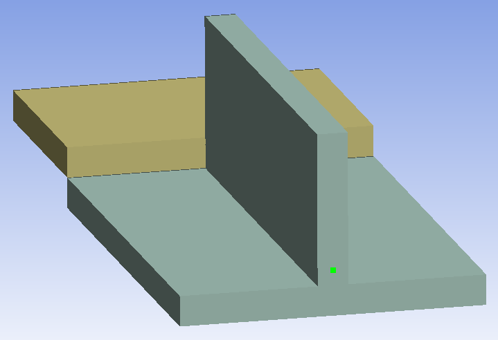
The image below shows two cross-sections assigned to two colinear lines. The default puts the centroid on the node, shown in green, but in this case, this is not desirable.
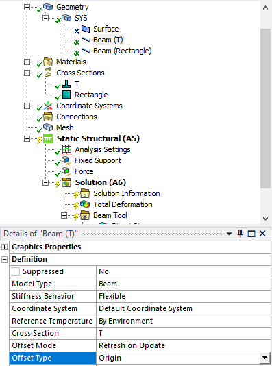
 Select the Beam(T) under the Geometry branch and in the Details window, change the Offset from Centroid to Origin.
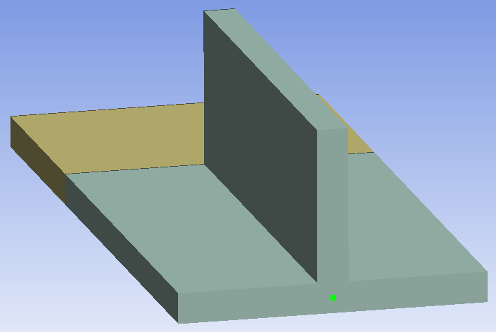
 Now the T cross-section aligns with the Rectangle cross-section.
 Viewing 8 reply threads
- The topic ‘Should the stresses in this stiffener actually exist?’ is closed to new replies.
Innovation SpaceTrending discussionsTop Contributors-
4838
-
1587
-
1386
-
1242
-
1021
Top Rated Tags© 2026 Copyright ANSYS, Inc. All rights reserved.
Ansys does not support the usage of unauthorized Ansys software. Please visit www.ansys.com to obtain an official distribution.
-
The Ansys Learning Forum is a public forum. You are prohibited from providing (i) information that is confidential to You, your employer, or any third party, (ii) Personal Data or individually identifiable health information, (iii) any information that is U.S. Government Classified, Controlled Unclassified Information, International Traffic in Arms Regulators (ITAR) or Export Administration Regulators (EAR) controlled or otherwise have been determined by the United States Government or by a foreign government to require protection against unauthorized disclosure for reasons of national security, or (iv) topics or information restricted by the People's Republic of China data protection and privacy laws.


