
TAGGED: compression-only-support, rigid-body, shell
-
-
October 23, 2020 at 9:49 am
bokaJ
SubscriberOctober 24, 2020 at 3:05 pmpeteroznewman
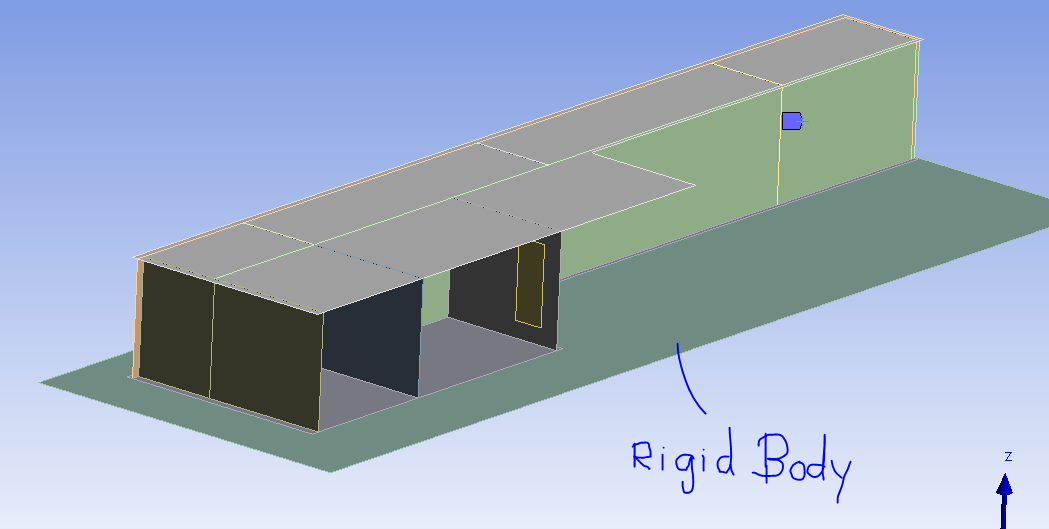
SubscribernDelete the Fixed Joint, Body-Body.nInsert a Fixed Joint, Body-Ground, and select only the Rigid Body.nInsert a Contact between the Rigid Body and the 11 faces of the floor of the structure. The Rigid Body face must be on the Target side. Make the Contact type be Frictional or Rough. A rough contact will not slide on the rigid body, but can separate. You want to see the blue color on the opposite side to what you show in the image above. You do this by setting the Contact Side to Bottom instead of Top.nUnder the Connections folder, insert a Contact Tool and Generate Initial Contact Status. The Frictional or Rough contact must show as Closed. nUnder Analysis Settings, turn on Auto Time Stepping. Set the Initial Substeps to 100.nOctober 27, 2020 at 12:11 pmSubscribernThank you very much for your quick and very helpful answer.nAs you can see in the following picture, the deformation looks as expected.n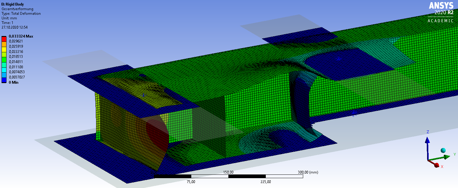 nBut there is a slight step through at some areas. In my opinion this should not be possible?nOn the picture below, you can see the details of the contact between the rigid body and the shell body.n
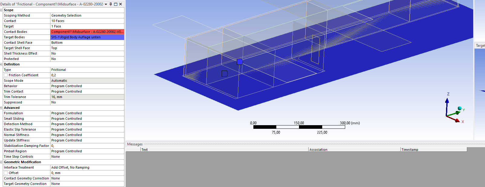 On the picture below you can see the initial information of the contact. n
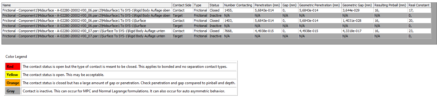 For the hickness of the shell and the rigid body I choose 15mm. But I put the rigid body directly on the shell, or should I leave a gap of 15mm(=7,5+7,5) between the shell and the rigid body?nWould you possibly so kind as to help me again with this problem?.Thank you a lot,nbokaJn
October 27, 2020 at 5:03 pmSubscribernYou can either put two surface bodies on the same plane and leave Shell Thickness Effect turned off, ornyou can put the two midsufaces 15 mm apart and turn on Shell Thickness effect.nIn either case, the thickness assigned to the surfaces is 7.5 mm.nContact algorithms allow a very small penetration to be used to compute the contact force needed to prevent large penetration. You can control the size of that very small penetration by altering the Normal Contact Stiffness Factor. The default value is 1, you can increase it by a factor of 10 or 100.nYou can insert a Contact Tool on the Solution branch and insert a Penetration plot on that tool. That will show the value of penetration as a contour plot. Note that the Deformation Result is often scaled to look 1000 times more that reality. Set the Result Deformation Scale to 1.0 (True Scale).n/forum/discussion/14332/deformation-scalenOctober 28, 2020 at 6:01 amSubscriberthank you very much sir!nthe maximum penetration is about 0,001mm.nI learned a lot from you!nnBest regardsnbokaJnViewing 4 reply threads
For the hickness of the shell and the rigid body I choose 15mm. But I put the rigid body directly on the shell, or should I leave a gap of 15mm(=7,5+7,5) between the shell and the rigid body?nWould you possibly so kind as to help me again with this problem?.Thank you a lot,nbokaJn
October 27, 2020 at 5:03 pmSubscribernYou can either put two surface bodies on the same plane and leave Shell Thickness Effect turned off, ornyou can put the two midsufaces 15 mm apart and turn on Shell Thickness effect.nIn either case, the thickness assigned to the surfaces is 7.5 mm.nContact algorithms allow a very small penetration to be used to compute the contact force needed to prevent large penetration. You can control the size of that very small penetration by altering the Normal Contact Stiffness Factor. The default value is 1, you can increase it by a factor of 10 or 100.nYou can insert a Contact Tool on the Solution branch and insert a Penetration plot on that tool. That will show the value of penetration as a contour plot. Note that the Deformation Result is often scaled to look 1000 times more that reality. Set the Result Deformation Scale to 1.0 (True Scale).n/forum/discussion/14332/deformation-scalenOctober 28, 2020 at 6:01 amSubscriberthank you very much sir!nthe maximum penetration is about 0,001mm.nI learned a lot from you!nnBest regardsnbokaJnViewing 4 reply threads- The topic ‘Shell slide on rigid body’ is closed to new replies.
Ansys Innovation Space Trending discussions
 Top Contributors
-
peteroznewman
 3587
3587 -
scabo
 1193
1193 -
Dennis Chen
 1086
1086 -
javat33489
 1068
1068 -
Shyam Prasad V Atri
952
Top Rated Tags
© 2025 Copyright ANSYS, Inc. All rights reserved.
Ansys does not support the usage of unauthorized Ansys software. Please visit www.ansys.com to obtain an official distribution.
-


The Ansys Learning Forum is a public forum. You are prohibited from providing (i) information that is confidential to You, your employer, or any third party, (ii) Personal Data or individually identifiable health information, (iii) any information that is U.S. Government Classified, Controlled Unclassified Information, International Traffic in Arms Regulators (ITAR) or Export Administration Regulators (EAR) controlled or otherwise have been determined by the United States Government or by a foreign government to require protection against unauthorized disclosure for reasons of national security, or (iv) topics or information restricted by the People's Republic of China data protection and privacy laws.


