TAGGED: reinforcement, shell, stress-singularity
-
-
July 14, 2023 at 2:51 am
Frank Astulle
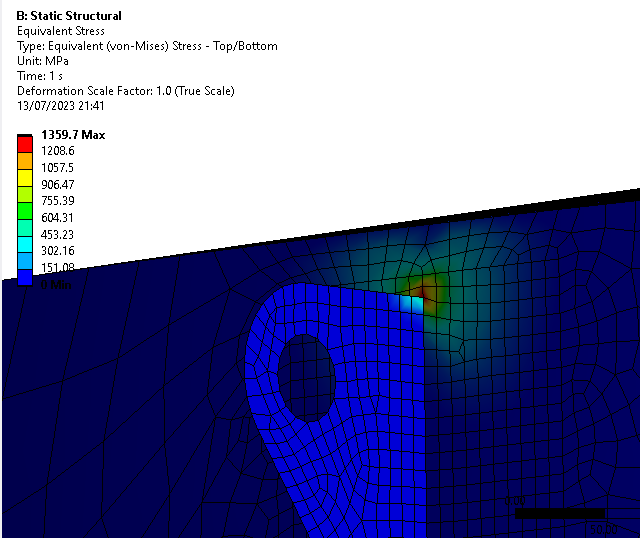
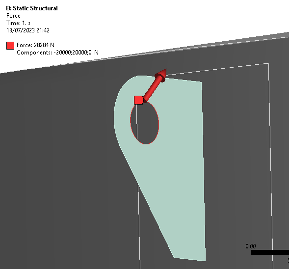
SubscriberHi everyone I tried to simulate a force inside a lifitng lug in a vessel. So I tried to do it with shell elements with a thickness of 6mm. So I`ve put 20000N in X and Y axes, and I believe that I get a singularity stress, because stress tends to infinity when when the mesh gets finer My question is ¿How I can determine the real strees in the shell of the vessel? And ¿how I can model a reinforcement pad with shell elements? I was thinking to split the shell and asign other thickness in the zone with reinforcement pad. How I can split the shell surface? I`ve tried to imprint face like a reinforcement plate but I can't asign another thickness in a imprinted face.

-
July 14, 2023 at 2:24 pm
dlooman
Ansys EmployeeIt's definitely a singularity at that location. Perhaps you should use solid elements for the lifting lug and the reinforcing pad.
-
July 15, 2023 at 4:48 am
mjmiddle
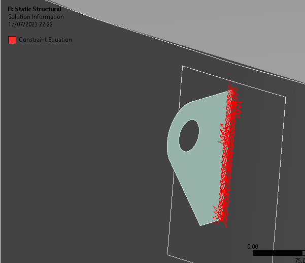
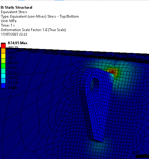
Ansys EmployeeThe real model has welds probably so has a taper at that corner. You can make small solid bodies with swept triangle shape to represent the welds, and use contact to connect to the solid.Or maybe an MPC bonded contact from edge-to-face can resolve the stress singularity, even without solid bodies to represent the welds, since the constraints will connect outward an additional layer of nodes.
If you want to specify a greater thickness to the shell just near the bond point, there are many ways to split the shell body or face. What CAD system does the geometry originate? You can draw a sketch line on the surface and split by that or split by a plane, or by two point selection on the boundary edges. Or you can split entirely in Mechanical using Virtual Topology. Right click on Model in the Outline to insert a Virtual Topology. This allows splitting and merging of faces and edges. If you split in the CAD Modeler you can split just the face so it is multiple faces in the same body, or you can split the body entirely, in which case, you can connect with shared topology if you use SpaceClaim or DesignModeler. In Mechanical you can, of course, set a different thickness on different bodies if you split the body entirely. If you split only the face, so as to have multiple faces in the same body, then you can right click in Mechanical on "Geometry > Insert > Thickness." This allows you to select faces and set different thicknesses for faces in the same body.
-
July 18, 2023 at 3:27 am
-
July 18, 2023 at 4:51 am
mjmiddle
Ansys EmployeeI'm not entirely convinced it's a stress singularity. Based on the direction of the force, you could have high stress and deformation in that pattern. Is it steel with a yield stress around 250 MPa? It is over yield, but not excessively so. We verify stress singlarities by making smaller elements at the suspected location to see if the stress keeps going up. In non-singularities, the stress may go up but does so asymptotically, aproaching a constant value.
-
July 18, 2023 at 7:27 am
ErKo
Ansys EmployeeHI
Just to add to mjmiddle and to do a mesh refinement study to see if it is a singularity - see this post about this:
(see section on welds/shells)
https://www.comsol.com/blogs/singularities-in-finite-element-models-dealing-with-red-spots/
All the best
Erik
-
- The topic ‘Shell Elements Stresses’ is closed to new replies.


-
5149
-
1836
-
1387
-
1248
-
1021

© 2026 Copyright ANSYS, Inc. All rights reserved.


