-
-
November 8, 2017 at 8:36 am
emirdegirmenli
SubscriberI am trying to analyze vibration characteristics of musical instruments which have a very thin wood plate. I can get similar results with using solid element but generally, researchers who work on musical instruments are using shell element and they say that you can get a reliable result with this method because a thickness of the plate is very small (2-3 mm) than its dimensions (360-460 mm). now, I am carrying out an experiment by using two rectangular plates (493x182x3 mm) on Ansys mechanical. First one is the only surface mashed with shell element (thickness is 3 mm), the second one is solid have same dimensions. As you can see attached images, if I choose structural steel for material, vibrations of two plates are similar. But I choose an orthotropic material such as wood, results do not match. additionally, results obtained from the solid element is closer to experimental data.
-
November 8, 2017 at 3:44 pm
peteroznewman
SubscriberPlease post an image of the material properties for wood (or an xml file exported from the database) and an image of the mesh.
How many solid elements are you using through the thickness?
Are you using solid-shell elements or just solid elements?
-
November 9, 2017 at 7:05 am
emirdegirmenli
SubscriberThank you, Peter, I've attached some images. Actually, I only drew one surface and one solid on SpaceClaim later click "generate mesh" in Mechanical and adjust the only size. I don't know differences between solid and solid-shell elements. Can you give me some advice I can research this issue, best.
material
mesh
results
-
November 9, 2017 at 2:39 pm
peteroznewman
SubscriberShell elements have equations built-in to calculate bending behavior since each node has rotational degrees of freedom to represent bending. Solid elements do not have rotational degrees of freedom, only displacements, so a single layer can't represent bending accurately. You need many solid elements through the thickness to accurately capture the bending behavior and match the results from a shell element model. Solid-Shell elements have bending equations added to them, but I'm not sure if a single layer through the thickness is adequate. Perhaps others will comment.
The image of the material properties is not legible. Either attach a file of the full res image or make your window narrow and only take a screen snapshot of the material properties.
Cheers,
Peter
-
November 10, 2017 at 7:42 am
emirdegirmenli
SubscriberThank you, Peter, I also anticipate to get better results from shell element but If you check last image (results) you will see that results obtained from solid (right side) element closer than shell element. Even I can't see one of bending modes by using the shell element. I've inserted new image of material properties. Actually, I've tried different material properties from another Ph.D. thesis but I can't solve the problem. Rectangular plate dimensions (Spruce): x:493 mm, y: 182mm, x: 3mm. experimental modal analysis results: two node line along x-axis: 105Hz, two node line along y-axis: 63Hz. I've obtained similar results by using solid element, 105,33 Hz and 62,36 Hz respectively. But when I use shell element, results are very different experimental data, 19Hz and no results respectively. Best
Emir
experimental results
FEM Results
-
November 10, 2017 at 2:44 pm
peteroznewman
SubscriberEmir, I notice in the Orthotropic properties, the Poisson's Ratio YZ is greater than 0.5 which I have never seen before. Please check that. For isotropic materials, 0.5 is the maximum possible value, which represents incompressible materials.
What support (if any) is in the Modal analysis? ANSYS will perform a modal analysis without supports, which is appropriate for structures floating in space. When you analyze structures with no support, the first 6 modes are zero, so to see the first two non-zero modes, you have to request 8 modes since the default is to compute 6 modes. Click on Analysis Settings and in the details pane, the first line is Max Modes to Find and type 9, then Solve.
I built a version of your model with no supports and used shell, solid-shell and solid elements, but used 20x50 elements along the edges instead of the lower element count of 8x20 you had.
Natural Frequency (Hz) for different element types using Orthotropic Material shown above.
Natural Frequency (Hz) for different element types using Isotropic Material.
Young's Modulus same as X direction above, Poisson's Ratio = 0.44.
Wow! Looks like you're onto something with the difference between Orthotropic and Isotropic properties for the Modal solver. Maybe others can comment?
For the experimental result you mentioned, how is the panel supported, how were the modes excited and how was the frequency measured? Do you have any experimental data to verify the properties in your orthotropic material model? ASTM D3043-00 "Standard Test Methods for Structural Panels in Flexure" describes how to measure the stiffness of thin strips in bending. You should try to validate your material properties by experimental means. You can also easily weigh a panel and measure its dimensions to calculate a density.
-
November 11, 2017 at 5:57 am
peteroznewman
SubscriberFor an isotropic material, Shear Modulus is calculated from Young's Modulus and Poisson's Ratio.
For Young's Modulus = 9.8E9 Pa and Poisson's Ratio of 0.44, Shear Modulus is 3.4E9 Pa.
The orthotropic material you show above has a Shear Modulus about 1/3 of an isotropic material.
The table below shows how the frequency of Mode 8 changes as the Shear Modulus is reduced.
The shell element mode 8 is affected while the solid element mode 8 is not affected by the Shear Modulus.
Mode 7 is the bending mode
while Mode 8 is a twisting mode that creates a lot of shear in the material.
The change in Mode 8 natural frequency with Shear Modulus provides confirmation that the shell elements are using this value appropriately, and that a single layer of solid elements are not. Shell elements are the right choice for a Modal Analysis of a thin structure with orthotropic properties that include lower values of Shear Modulus when there is a significant shear mode present.
Your musical instrument is not floating in space, so a more appropriate boundary condition might be for the rectangular plate to be either simply supported or fixed on the edges. The best boundary condition for the model is the one that represents the experimental setup.
-
November 13, 2017 at 8:42 am
emirdegirmenli
SubscriberThank you very much, Peter, you gave very important information. Twisting modes are very important for us, so I will use shell element. Generally, we use modal analysis both free conditions (ex. violin plate tuning) and full body (top glued body or ready for playing). I know full body FEA is very complicated because we have to consider other parameters such as coupling together the top, back and air inside (especially Helmholtz resonance). So First I've focused on the free plate analysis and later, I will be interested in the full body resonances by using FEA.
As I understand that there is a problem with identifying the material properties of wood. I can measure longitudinal and transverse elasticity by using resonance method ( http://ukuleles.com/?page_id=793). This method is very useful for instrument maker because getting results is easy, quick and cheaper than other techniques. But I can't obtain Poisson ratio or Shear modulus. So I need to borrow this data from other works, and I think this is causing a problem. Best,
Emir
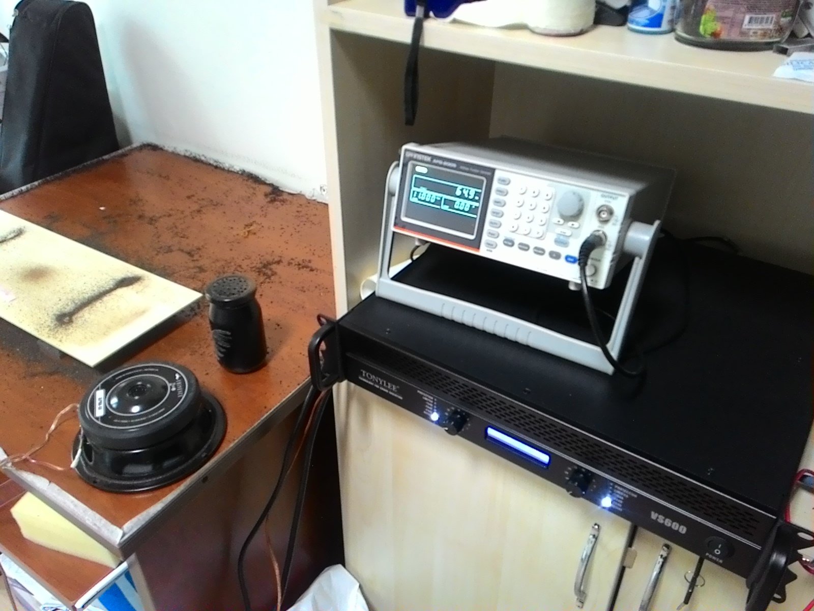
from my measurement setup (Chladni Method):
Elasticity results according to Resonance Method,
Ey Young's modulus, h thickness, Fy bending mode frequency (dividing y-direction), Ly y-dimension length, d density (Another direction modulus can be found by using same formula)
Ex= 9,9e6 Pa
Ey= 5,1e8 Pa
Exy= 7,5e8 Pa
-
November 14, 2017 at 4:53 am
peteroznewman
SubscriberThanks for the pictures Emir, that really helps me to understand your setup.
You show E.xy but that is not an entry for an Orthotropic material and I don't know what that means, perhaps that is G.xy?.
Poisson ratio has no effect on the natural frequency of shell elements using Isotropic materials, based on a test in ANSYS.
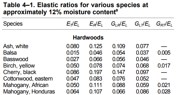
I found a paper that reports the Othotropic elastic properties of many types of wood. That paper uses the terms L, R and T to represent Longitudinal, Radial and Transverse directions in the wood. If you assign the x axis to Longitudinal, which axis is going to be Radial? Aren't most sheets of wood going to have the Radial direction be the thickness direction? Is thickness Z in your definition? I see that the Poisson Ratio in this paper is > 0.5 in many cases. That is because they have measured the shear modulus G. The paper also shows the magnitude of Young's Modulus relative to the Longitudinal axis (grain direction).
Based on this table, I would expect to see values of E.y and E.z to be a small fraction of E.x
The table for Poisson Ratio shows that there are different values depending on which direction is being stressed.
Note that the value for LR is not equal to the value for RL.
The Orthotropic material model in ANSYS can only handle the case where LR = RL.
I don't know how you can incorporate this data in ANSYS, maybe others will comment?
Here is a totally different idea: use Euler beam equations that only include the parameter EI to characterize the bending stiffness of the beam. You could use narrower strips of wood. As the strip gets narrower, the first mode will not be a twisting mode. b can be much smaller than 182 mm for this idea.
The equation for the first natural frequency of a free-free Euler beam is:
where I searched for the value of E that would deliver the 65 Hz from your experiment.
When I type this value into an Isotropic material, ANSYS calculates a frequency of 65.1 Hz.
The shear modulus is automatically calculated for an isotropic material but does depend on Poisson ratio.
Say the first test had the grain running parallel to the length of the rectangle to measure E.x.
Cut and test another piece where the grain runs parallel to the width of the rectangle to get an estimate of E.y from its first natural frequency.
Create an Orthotropic material by using the same value as E.y for E.z since these directions are both across the grain. Use the values of Shear Modulus calculated by the Isotropic material. However, Shear Modulus is affected by Poisson Ratio in the Isotropic material. I would use the same value of Poisson Ratio for XY and XZ.
I recommend you carefully check the thickness is exactly 3 mm. If the thickness is off by only 0.1 mm, the value of E changes by nearly 7%
What do you think?
Regards, Peter
-
November 14, 2017 at 11:17 am
emirdegirmenli
SubscriberThank you, Peter, for my model longitudinal (L) direction is x-axis, Radial (R) is y-axis and Tangential (T) is z-axis. I calculated shear modulus as your advice and tried these properties on modal analysis but I cant obtain compatible results. Especially when I use shell element, results are far away. Later I use another piece of wood which has different physical properties and made new tests by using FEM and compare them the experimental result. I had to make some adjustment on Ex, Ey and Share modulus xy. And I obtained results which you can see the image by using solid element. Shell element results are still incompatible. what do you think about a solid element can be used as results. Best, Emir
New material properties (I borrowed Poisson ratios from doctoral thesis - In the thesis, it is mentioned that the shell element is the best method for thin plate

-
November 14, 2017 at 12:01 pm
peteroznewman
SubscriberVery interesting Emir. Here is what I found in the Online Help.
5.2.6. Shell Element Coordinate System
The element coordinate system for all shell elements has the z axis normal to the plane. The element x axis is in the plane, with its orientation determined by one of the following:
The ESYS command
Side I-J of the element
Real constants
Solid elements
The default orientation is generally parallel to the global Cartesian coordinate system.
Conclusion: The different results between Shell and Solid Elements is due to the orthotropic material properties for each model pointing in different directions!
The shell elements have the x axis normal to the I-J side of the element, while the solid elements have the x axis aligned with global x. Next question is how to use the ESYS command in Mechanical to override the shell element default. I will look into that and post a reply.
Regards, Peter
-
November 14, 2017 at 12:41 pm
peteroznewman
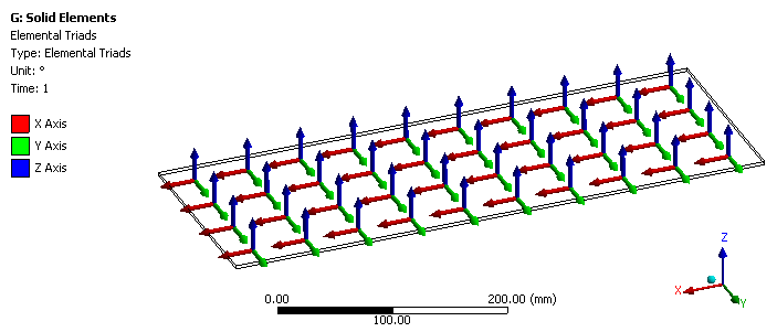
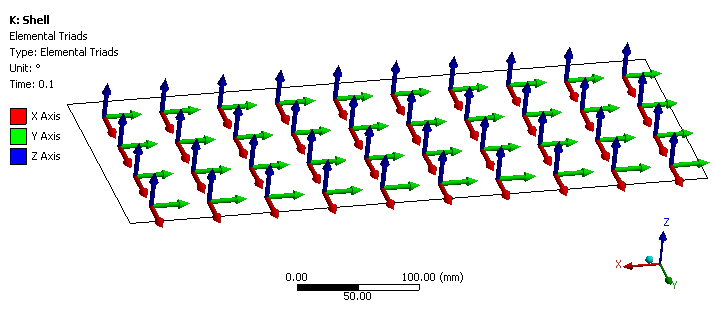
SubscriberEmir, you can plot the Element Triad only after you go to Analysis Settings, Output Controls and say Yes to General Misc.
Here is the solid element triad:
Here is the shell element triad:
I think this answers why the orthotropic shell and solid elements are giving such different results.
Regards, Peter
-
November 14, 2017 at 2:13 pm
-
November 14, 2017 at 4:30 pm
peteroznewman
SubscriberYou're welcome Emir!
Here is the shell mesh Element Coordinate System override method.
Create a new Coordinate System using Manual with ID = 12.
Then add a Command Snippet to the Modal branch like this.
Here is the text of that command:
/PREP7
EMODIF,ALL,ESYS,12
FINISH
/SOLU
It worked for me!
Best regards, Peter
-
November 15, 2017 at 7:13 am
-
November 15, 2017 at 12:28 pm
peteroznewman
SubscriberDear Emir, that's great news!
Good luck with your studies,
Best wishes, Peter.
-
- The topic ‘shell element with orthotropic materials gives very different results from experimental data’ is closed to new replies.


-
5059
-
1770
-
1387
-
1248
-
1021

© 2026 Copyright ANSYS, Inc. All rights reserved.


