Hello, I'm trying to compare the analytical result with the simulation result for the shear stress of a bolt.
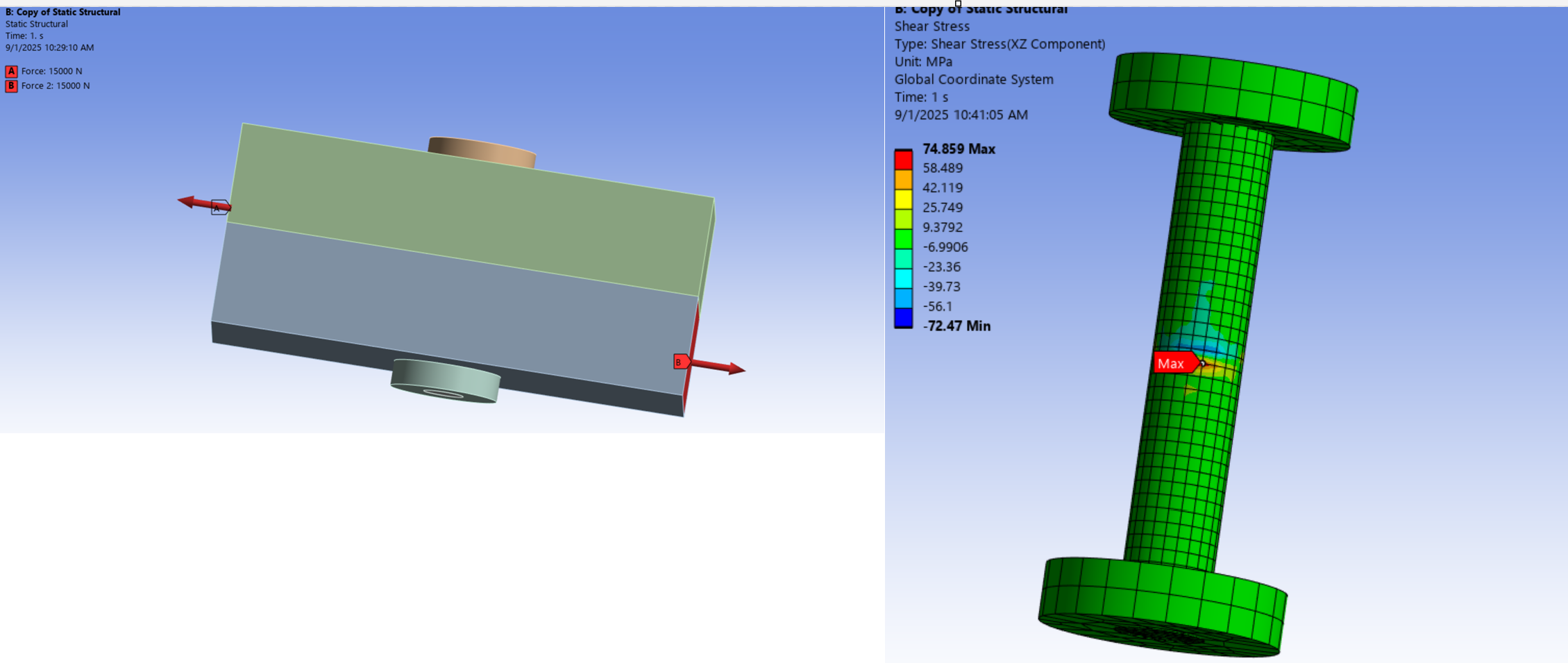
The bolt has a diameter of 16 mm. It is located at the center between two sliding plates. One end of the top plate (left side) is subjected to a 15 kN force, while the opposite end of the bottom plate (right side) is also subjected to a 15 kN force. The calculated analytical result for shear stress is 74.6 MPa.
I ran the simulation in Ansys. The contacts were set to frictionless for the sliding parts only and bonded for the other parts. The results I obtained with different mesh sizes are:
20 mm mesh size → 50 MPa
10 mm mesh size → 60 MPa
5 mm mesh size → 66 MPa
2.5 mm mesh size → 74.8 MPa
1.25 mm mesh size → 119 MPa
I thought I was on the right track since the 2.5 mm mesh gave a result very close to the analytical value. However, I expected the 1.25 mm mesh to give an even closer result t0 74MPA , but instead, it gave a much higher stress.
Is there something wrong with my setup? Thanks