-
-
December 17, 2017 at 12:44 am
peteroznewman
SubscriberI looked at a model jonnyflowers was working on and wrote some suggestions that may be helpful. The model has one body, a silicon chip, inside a large rubber block.
First Observation is to set Topology to Shared in SpaceClaim, and delete the Contact in Mechanical. That creates the bond between the silicon chip and the rubber by having them share nodes instead of adding contact elements. However, contact elements can be useful if you want to get the pressure at the interface. If you need the contact, then create a New Component and put the silicon chip in that new component, leaving the other component to hold all the sliced parts of the block.
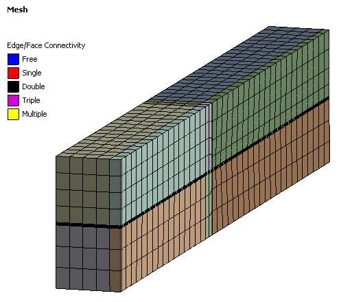
Second observation is you can have a better mesh within the Student limit if you slice the block up around the silicon chip, so that hex meshing can be used instead of tet meshing. The section view below show the silicon chip in the center of the block.
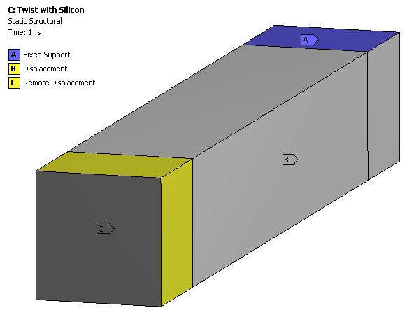
Third observation, you can reduced the number of equations in the model if you slice off the end where you are applying the remote displacement on four side faces, and just apply the remote displacement on the cut end face.
Last observation is to change Automatic Time Stepping to On instead of Program Controlled, then set initial substeps of 40, and limit the maximum substeps to 20. That will allow the solver to have more successful converged substeps and spend less time bisecting to smaller substeps after taking too large of a substep.
I incorporated these suggestions in the attached ANSYS 18.2 archive. It will solve in 394 iterations, which took 10.8 minutes on 16 cores, but 40.6 minutes on 2 cores.
-
December 18, 2017 at 11:50 am
jonnyflowers
SubscriberSo I need to have the pressure and forces at the interface with the block in the middle. Could you go into a little more detail on what you mean by keeping the shared topology block there and adding another one please?
Thanks
-
December 18, 2017 at 11:57 am
jonnyflowers
SubscriberAlso the reason I modelled the full block is I have been using the single model for multiple simulation conditions, the twist was just one that happened to not use the end.
-
December 18, 2017 at 5:18 pm
peteroznewman
SubscriberRight, all the suggestions may not apply to your overall analysis goals.
Here are the steps to convert from the model attached above where all the bodies share topology, which looks like this, where the top level is set to share and the lower level components are set to none...
Â
to this configuration where the top level is set to none and the Block is set to share.
Then you can put back the contact of the chip to the block faces that touch it.
-
December 29, 2017 at 12:23 pm
jonnyflowers
SubscriberSo I carried out some slicing on a more complex model but apparently spaceclaim has a an upper limit for the number of bodies I can have?
My model has 72 bodies now and I am being informed by an error message that this number cannot exceed 50?
I cannot find any documentation of this behaviour anywhere?
-
December 29, 2017 at 12:26 pm
-
December 29, 2017 at 1:14 pm
peteroznewman
SubscriberSorry Jonny, according to this post, that is the limit for the Student license.
No such limit exists for the Commercial or Research licenses.
-
December 30, 2017 at 11:02 am
Raef.Kobeissi
SubscriberWhats the limit for structural mechanical in terms of number of elements? -
December 31, 2017 at 1:21 am
peteroznewman
SubscriberThe Student license limit is nodes+elements < 32,000 for Structural models.
Cheers,
Peter
-
January 3, 2018 at 2:09 pm
jonnyflowers
SubscriberIs there a way to get all the meshes to line up so that contact is more reliable?
For some reason mesh connection is greyed out
-
January 3, 2018 at 3:55 pm
peteroznewman
SubscriberYou don't want mesh connection, that merges coincident nodes (even moving nodes to make them coincident), which is just like the shared topology method that needs no contact. You want contact.
The way to make the mesh line up is to put the same mesh sizing controls on the coincident edges of the silicon chip and the rubber cavity for the chip. Use the Hard setting for Behavior to force the mesher to respect the sizing control and use Number of Elements. That way, you will match the edges and if both faces have Face Meshing, the face nodes should line up also.
-
- The topic ‘Shared Topology and Slicing Body to Improve Mesh’ is closed to new replies.
-
4102
-
1487
-
1318
-
1156
-
1021
© 2025 Copyright ANSYS, Inc. All rights reserved.