-
-
August 22, 2024 at 3:50 am
Sept
SubscriberI am reaching out to see if I could get some guidance on setting up a coplanar waveguide simulation to extract S-parameters, propagation constant values, etc...
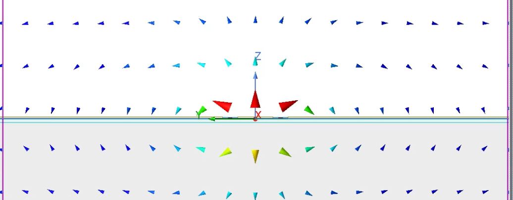
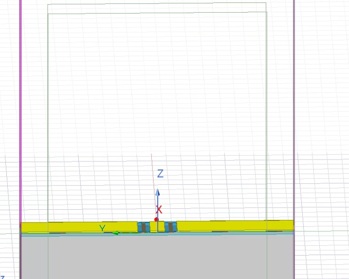
The current setup consists of using modal network solution along with the excitation being wave ports (first picture posted). The simulation space is enclosed within an airbox with no boundary conditions.
In the CPW example I have seen given by HFSS, perfect H boundaries are given to surfaces where the ports are as well as radiation boundaries for the airbox. Given that I am running the simulation as a modal network solution should I follow the same boundary conditions?
I also have noticed that the port modes are slightly different as shown in the images I have uploaded. Is this okay?
-
August 27, 2024 at 5:19 am
dushyant.marathe
Ansys EmployeeHi Elliop,
Thanks for posting your query on Ansys Learning forum. I could see from second image that you have setup a CPW line with two side grounds.
There are certain recommendations for exciting CPW lines with wave ports. They are regarding the sizing of wave ports:
Wave Port Size:
A Rectangular Apertured with Port width and Hight should no less than 3*(2g+w) and 4*h respectively.
Where, h= dielectric height, g = spacing between signal and side ground, w = width of signal trace.
Port should be centred horizontally on CPW trace. The port should be exposed to simulation volume or if internal need to be capped by PEC block. The wave port outline should contact all side grounds and size should not exceeds lambda/2 in any dimension to avoid rectangular waveguide excitations.
In your case based on description, I understand that line structure is inside simulation volume therefore PEC caps are required for wave ports. You can know more about this from HFSS help PDF.
Kindly assign radiation boundary to air box/simulation box enclosing line structure.
Thanks,
-
- You must be logged in to reply to this topic.


-
4683
-
1565
-
1386
-
1242
-
1021

© 2025 Copyright ANSYS, Inc. All rights reserved.


