-
-
November 8, 2023 at 1:37 pm
Jason Sum
SubscriberNA
-
November 8, 2023 at 4:39 pm
Rob
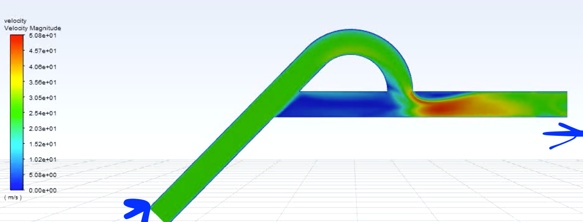
Forum ModeratorThat looks like the flow didn't develop very well. Can you post the velocity contour so we can see what's going on? As an aside the angle and shape of these sorts of valves is very important, small deviations can have significant effects on the results: power fluidic devices use this to control flow.
-
November 10, 2023 at 5:32 pm
Jason Sum
SubscriberMy trial on this T45 single-stage tesla valve is just for myself to understand the flow physics behind when there is pressure difference driving the inflow.
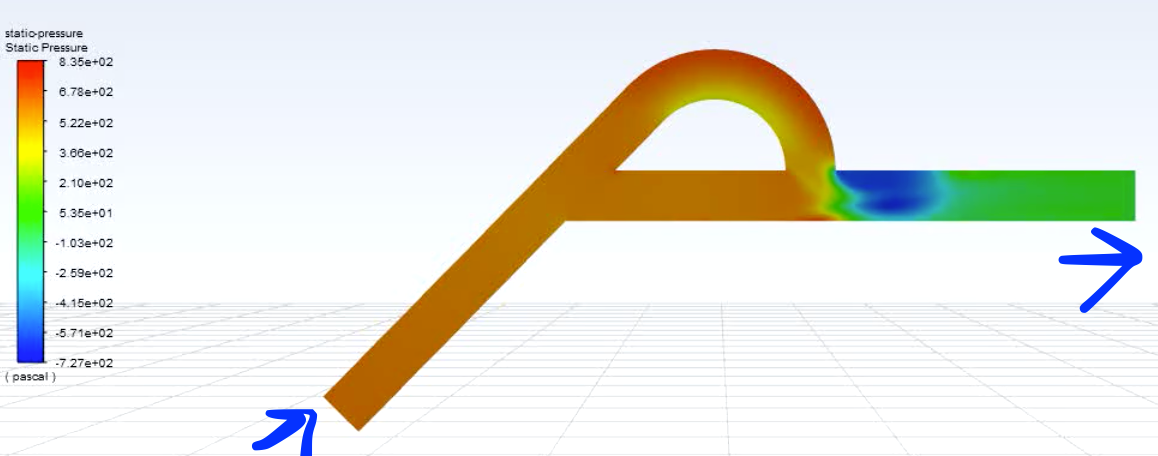
Below are result of transient velocity and pressure contour plots under convergence:
My concern is, the passive scalar of incoming air shown in previous comment gradually filling up the valve, but not similar to the result from the Holzman CFD Youtube video (only "concentration/portion" of incoming air tracing). I would like to know is sth wrong about my setup of UDS. Thank you!
-
November 14, 2023 at 3:07 pm
Rob
Forum ModeratorIs this for water, and what is the scalar diffusivity?
-
November 14, 2023 at 4:58 pm
Jason Sum
SubscriberIt is air flowing from inlet of the valve (single phase). I set scalar diffusivity as 1, following some online videos on setting, not sure if it is not making sense. I would like to know the way to obtain the visualised result like the one from Holzman CFD Youtube video as shown above. Thanks for the guidance!!!
-
-
November 14, 2023 at 5:11 pm
Rob
Forum ModeratorAh, that'll explain it. The scalar is diffusing far too much. Treat the scalar like a species, and divide the typical value for that species diffusivity by the fluid density (scalars don't really have units). Liquids will be diffusivity of 1e-9 to 1e-10 or so - look it up as I usually have to.
-
- The topic ‘NA’ is closed to new replies.


-
4803
-
1576
-
1386
-
1242
-
1021

© 2026 Copyright ANSYS, Inc. All rights reserved.


