-
-
November 29, 2021 at 3:35 am
tumulpurwar
SubscriberHey there is any command, coding we can Incorporate to select lot of edges on both extreme ends , say like in case of fixed boundary condition on both side.
I am looking for automating this tedious procedure.
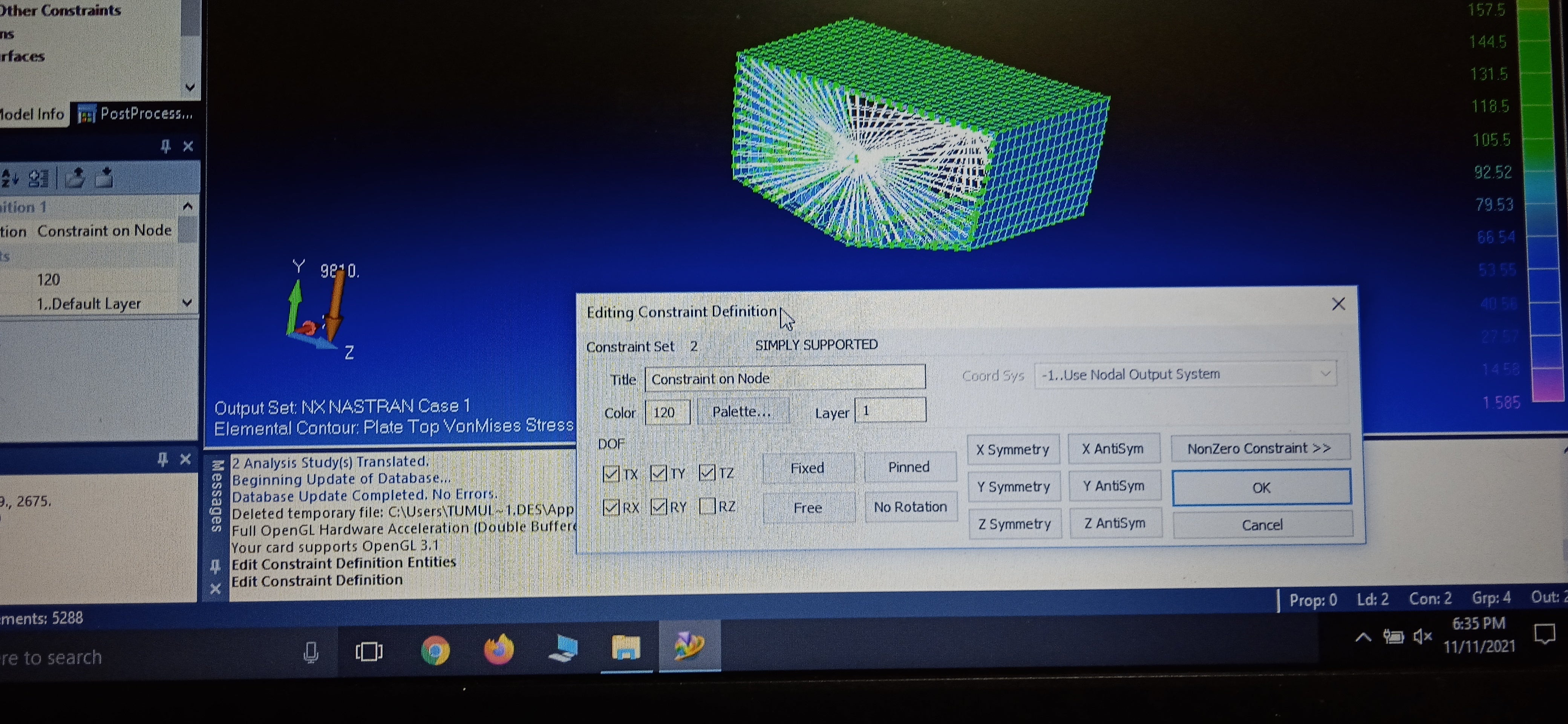
See photo below for rigid element, we need select so many edges, it's very tedious task.. Should we automate.
Any help?
November 29, 2021 at 4:05 ampeteroznewman
SubscriberIn Mechanical, there is a Box Select Mode. Enable that instead of the Single Select that you are currently using.
 Change the view so that all the edges you want to select are on one vertical (or horizontal) line. Draw a box around them. Done.
Note that Box Select work differently when you draw the box from left to right than when you draw the box from right to left. In the first case, only lines that are completely inside the box are selected, and lines that cross the box are not selected. In the second case, the lines that cross the box are also selected.
November 29, 2021 at 4:49 amtumulpurwar
SubscriberAwesome... So greatful.
I always wait for your comment.
Thanks a lot
November 29, 2021 at 5:26 amtumulpurwar
SubscriberIs it problem, Peter, if quad mesh fail on one face, can I still proceed for stress results?
November 29, 2021 at 6:01 amtumulpurwar
SubscriberHello Peter
With our last discussion in old 25% slice hull topic.. You told
If you know the bending moment at the 25% station of the hull, you can apply that as a moment to the remote point as a Moment load about Z. Use the same remote point in the Remote Displacement but leave RZ Free
I applied.. But it's saying.. Solver pivot error
November 29, 2021 at 10:10 pmpeteroznewman
SubscriberIf the meshing software fails to create a quad only mesh on a face, let it use triangles on that face. You want a mesh on that face, you don't want no mesh.
I found that you can't apply a moment to a remote point at the center of a cut section. You can apply the moment directly to the edges of the cut section.
Solver Pivot error is because some part of the structure is not connected to ground in six DOF. Drag and Drop a Modal analysis onto the Model cell. Drag and drop the boundary conditions applied in the Static Structural into Modal branch. Change the Modal to request 10 modes instead of 6 then solve. If you get six modes with nearly zero frequency, those will show the unconnected part moving around.
November 29, 2021 at 11:15 pmtumulpurwar
SubscriberThankyou very much for answer, but as I used Share topology in spaceclaim, still there can be chance that assembly parts are not connected well? (I mean share topology is for mesh connection I guess, not on level of geometry connection)
What the software has to do with geometry, when it has to calculate all in terms of mesh?
Thanks
November 30, 2021 at 12:49 amtumulpurwar
SubscriberNormally in femap, one of my friend did same kind of analysis, there we can apply moment about rigid point at the centre of cut section.
I am not sure, if I apply moment directly to cut section, how it will distribute moment to all edges of sliced section? Equally distribute or how?
If we can't use remote point scoped to moment and than this remote point scoped to remote displacement.
Also still I will need to let remote displacement condition remain applied on both side of slice hull cut section (leaving only RZ free on both sides) , along with direct moment on one cut section of sliced hull, right?
November 30, 2021 at 2:38 amtumulpurwar
SubscriberI solved modal analysis, I don't have zero frequency vibration. Thanks
Now it mean boundary conditions problem, I guess with pivot error in static structural?
November 30, 2021 at 4:31 ampeteroznewman
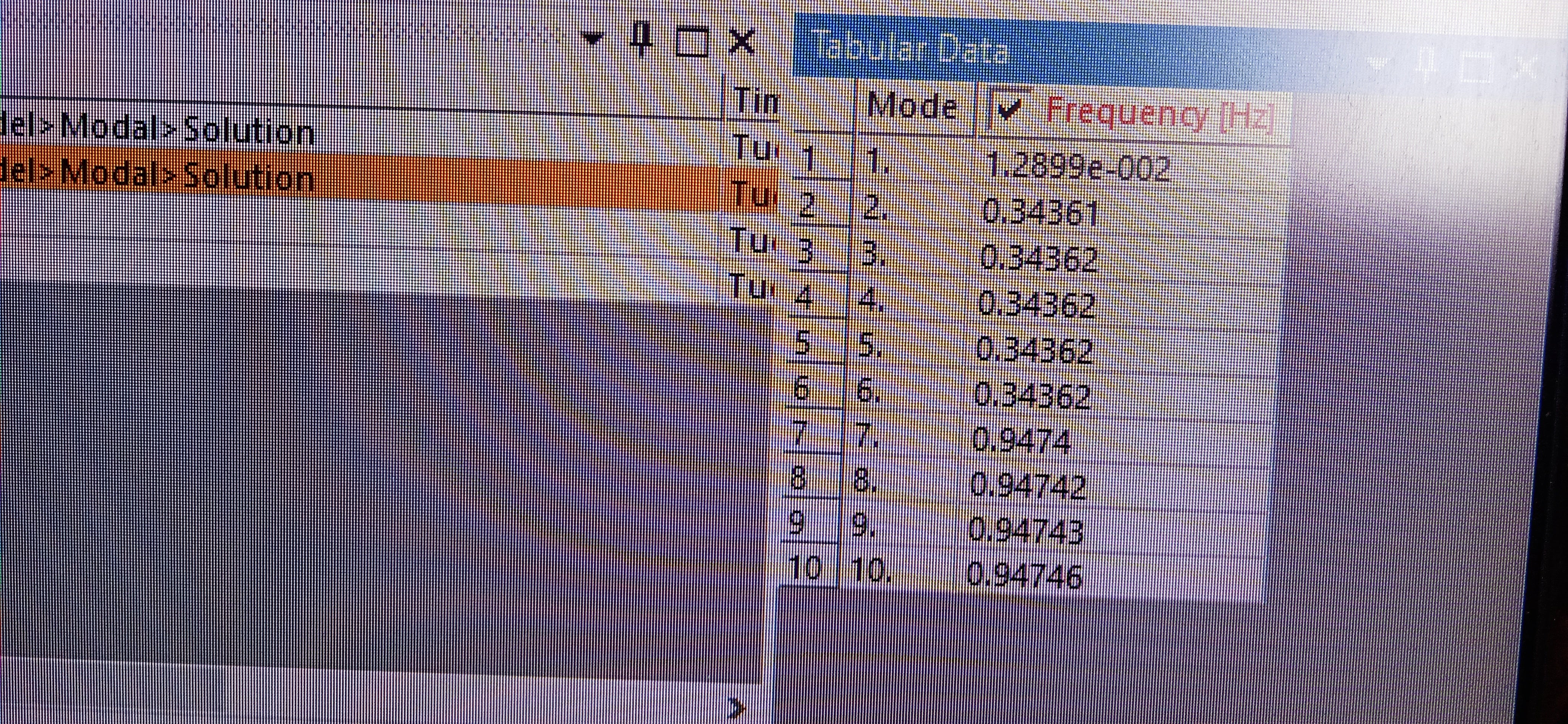
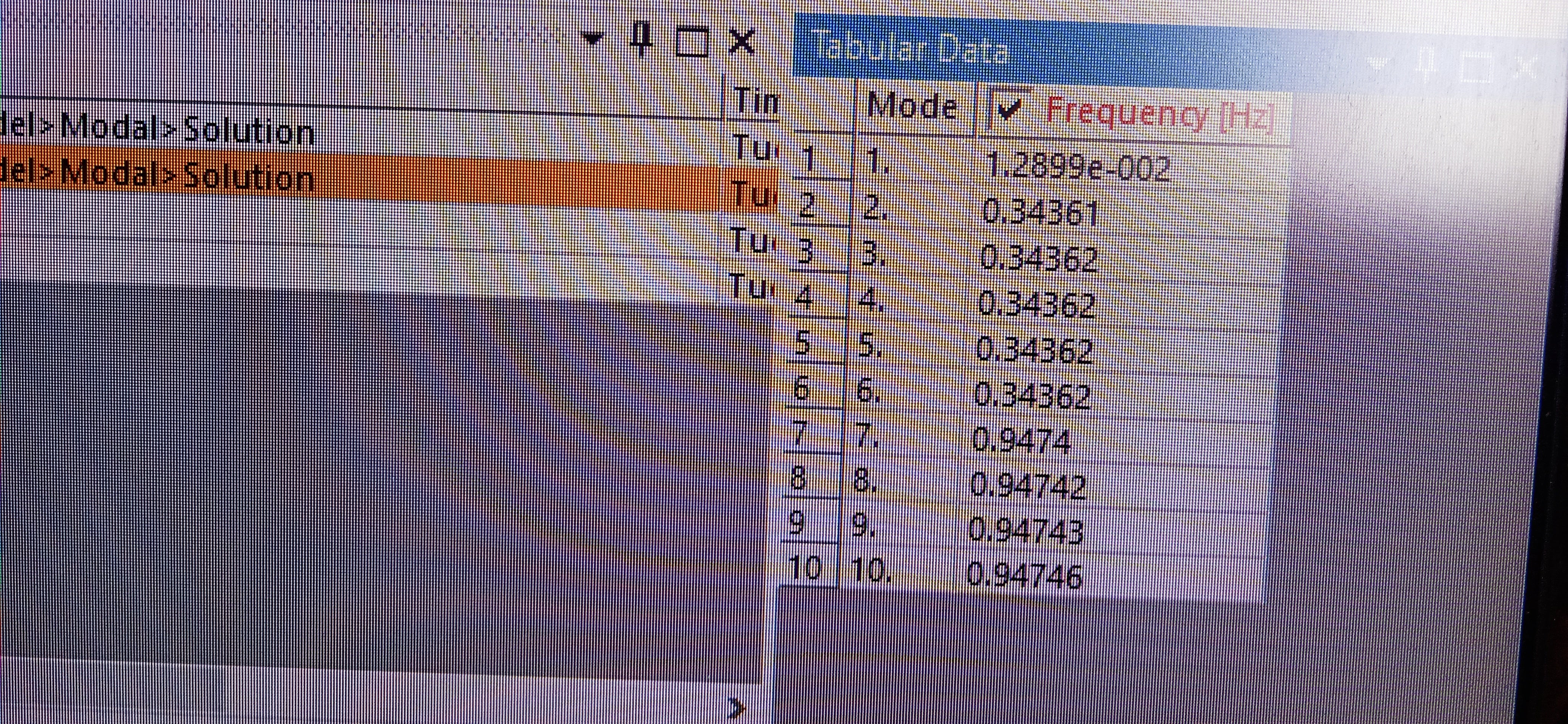
SubscriberPlease show the modal frequency results.
November 30, 2021 at 6:11 amtumulpurwar
SubscriberHere is it
My boundary condition ,which modal analysis took
Both sliced ends RY free all other fixed in remote displacement

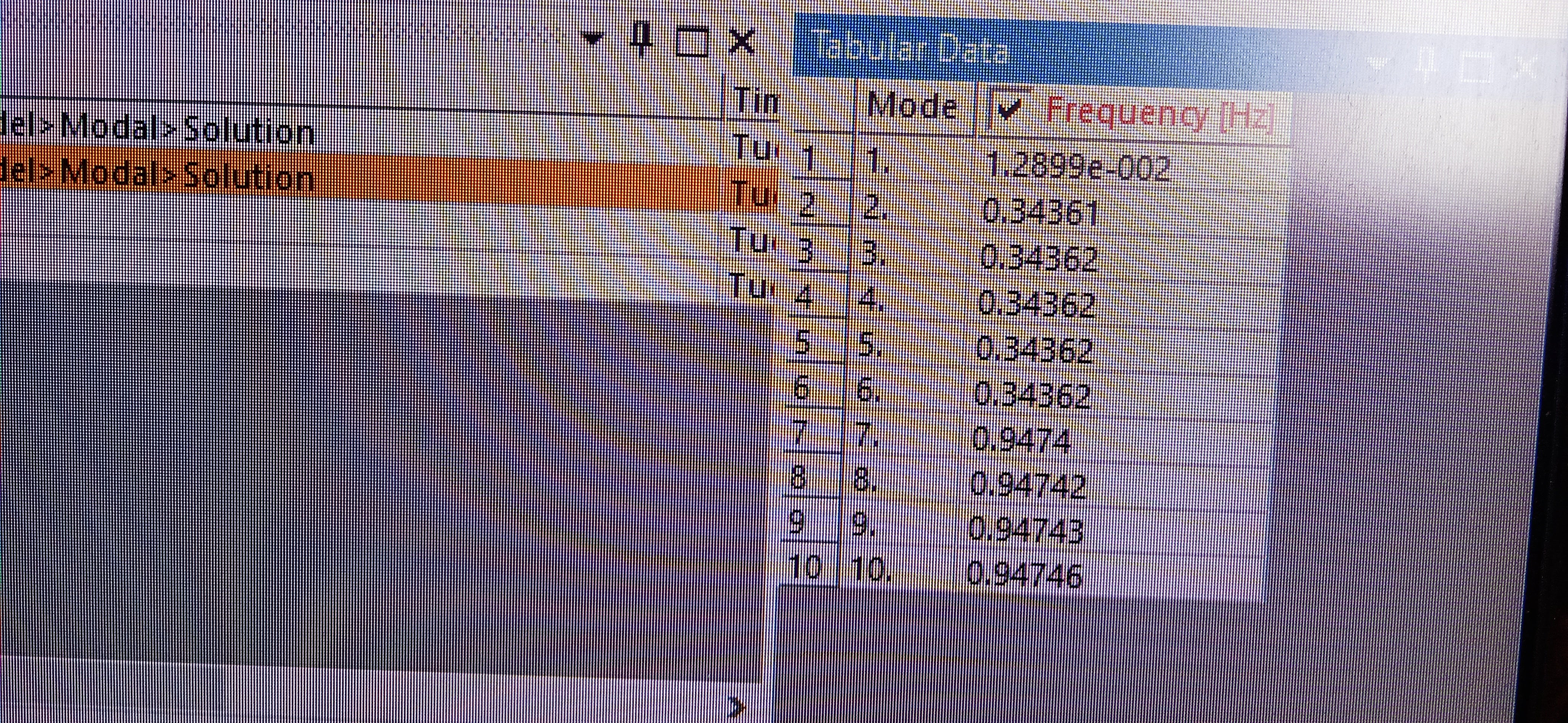
But if I animate, the whole structure kind of rotate about free axis Y
And if do static structural analysis, it giving heavy deformation in boundary condition sliced ends, and even some structural parts flying out.
My boundary condition in structural static also include
Loads, point loads on deck of heavy crane
And left sliced cut section with direct moment value in sagging condition
What you would suggest?
Thanks peter
November 30, 2021 at 6:19 amtumulpurwar
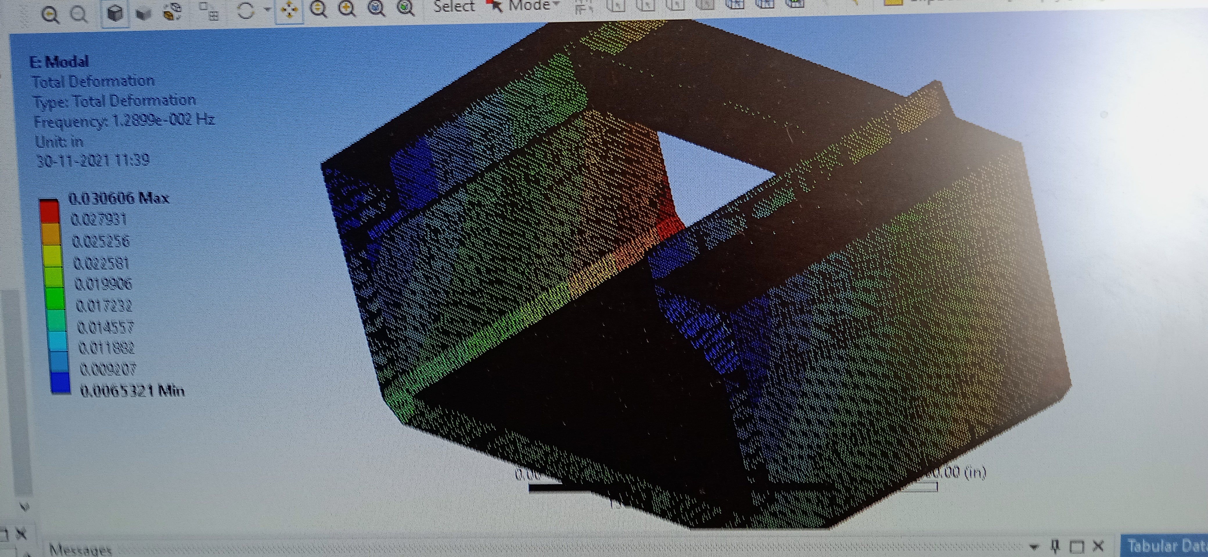
SubscriberHere are the photos for modal analysis. If I play animation, it shows rotation of structure of ship about Y axis.
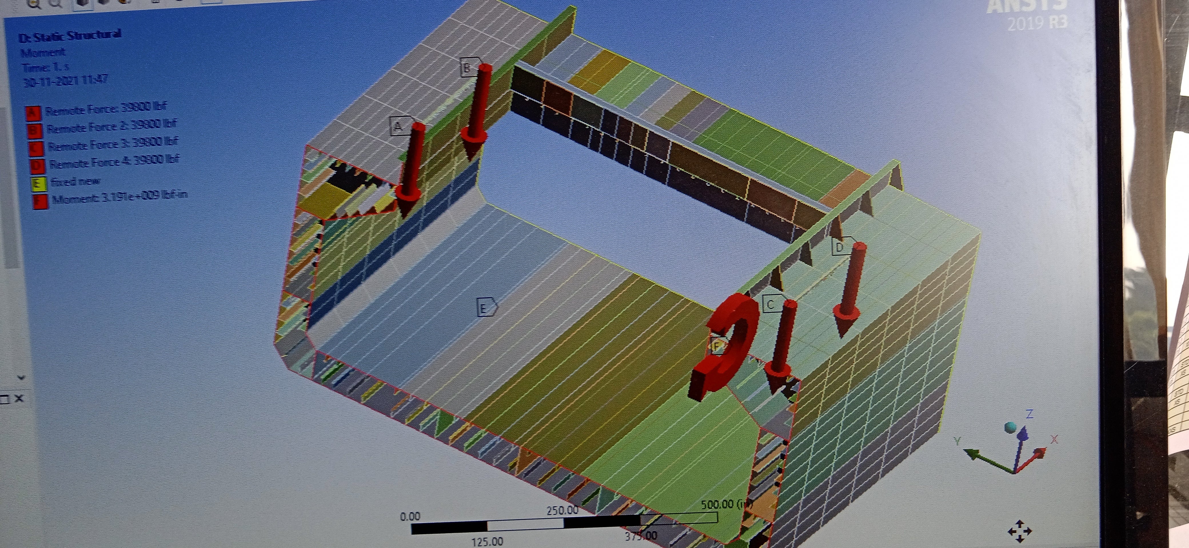
In static structural analysis I found, that structure members were getting heavy displacement, almost came out few of them from structure. My boundary condition are
Remote displacement both ends with RY free, rest 0
Loads: point loads as shown in photo of heavy crane over deck
And left sliced cut section with moment value using moment option, ( no more remote point scoped, as you suggested in last comment.)
November 30, 2021 at 6:27 amNovember 30, 2021 at 6:31 amNovember 30, 2021 at 6:31 amNovember 30, 2021 at 11:05 amNovember 30, 2021 at 11:05 amNovember 30, 2021 at 1:20 pmtumulpurwar
SubscriberHello Peter
If you can respond? Thank you waiting hopefully for your comments.
Sorry for photos attached multiple time, some phone issue.
December 1, 2021 at 1:02 amtumulpurwar
Subscriber
December 1, 2021 at 1:29 ampeteroznewman
SubscriberIf parts of the structure are flying out in the Modal animation, then the structure is not properly connected.
If the structure is rotating about the Y axis in the Modal animation, then the structure is not properly supported.
Please use the Windows Snipping Tool to take screen snapshots. Don't use your phone camera.
December 1, 2021 at 4:13 amtumulpurwar
SubscriberHello peter thanks for response, yes next time i will remember that.
The animation was from modal analysis
it was the boundary condition you told, what boundary condition i should apply than?
please i need your help
and also i should orient shell orientation in structure like in my project...i selected all bodies under shell orientation tab, than all faces, than one edge to give direction to x axis..but when i generate orientation message error tells:
The Element Orientation object has one or more elements whose computed edge guide axis and surface guide axis are parallel to each other.
The Element Orientation object has scoped edges that are not connected. The scoped edges have to be connected.
do i need selcet all girders seperately than deck and shell of this ship?
December 1, 2021 at 1:22 pmtumulpurwar
SubscriberHello peter
If the structure is rotating about the Y axis in the Modal animation, then the structure is not properly supported.
What boundary condition I need to use? Please help
I used your boundary condition which you told in our long discussion in another post.
With your answer atleast I can than proceed to further steps.
December 1, 2021 at 3:59 pmDecember 1, 2021 at 4:00 pmDecember 1, 2021 at 4:00 pmDecember 1, 2021 at 4:00 pmDecember 1, 2021 at 4:00 pmViewing 26 reply threads- The topic ‘Selecting boundaries edges’ is closed to new replies.
Innovation SpaceTrending discussionsTop Contributors-
4939
-
1639
-
1386
-
1242
-
1021
Top Rated Tags© 2026 Copyright ANSYS, Inc. All rights reserved.
Ansys does not support the usage of unauthorized Ansys software. Please visit www.ansys.com to obtain an official distribution.
-
The Ansys Learning Forum is a public forum. You are prohibited from providing (i) information that is confidential to You, your employer, or any third party, (ii) Personal Data or individually identifiable health information, (iii) any information that is U.S. Government Classified, Controlled Unclassified Information, International Traffic in Arms Regulators (ITAR) or Export Administration Regulators (EAR) controlled or otherwise have been determined by the United States Government or by a foreign government to require protection against unauthorized disclosure for reasons of national security, or (iv) topics or information restricted by the People's Republic of China data protection and privacy laws.

