-
-
December 16, 2021 at 1:13 pm
Dor
SubscriberHi,
I hope this is the right place for my question.
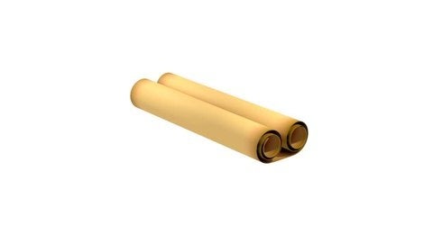
I've attached a photo of scrolled paper. Lets imagine one takes this scrolled paper and then opens it on a table.
December 16, 2021 at 2:11 pmpeteroznewman
SubscriberBack in the last century, many people had the experience of handling photographic film, which has similar behavior as the scroll of paper you describe. Some may have handled a roll of photo paper which also scrolls up after being pulled off the roll and laid flat. The scroll up forces are caused by the coating on one side of the backing media (film or paper) having a coating stress. The coating is applied as a liquid, and as it dries, it shrinks, generating the coating stress. The stress is often the same in any direction on the surface, the scroll forms along the long direction of the strip of paper because that is the lower energy state of the system, but you can sometimes hold a short length of it flat and get it to buckle into curling across the width. One property you need to know is the coating stress.
The following is from this paper: http://rosakis.caltech.edu/downloads/pubs/2007/160%20On%20the%20Stoney%20formula%20for%20a%20thin%20film%20substrate.pdf
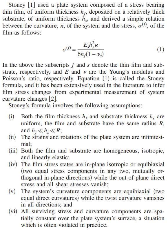 You have to measure the radius of curvature of a strip of paper. This is not simple, since you can't lay it flat on the table to measure as gravity would change the measurement. You need to have the strip with the narrow dimension vertical, but you can't rest the long bottom edge on the table, as the friction with the table will change the measurement. The trick is to support the center of the long edge of the strip on a short pad to keep most of the long edge from dragging on the table and have a pair of vertical rods supported in the pad with a gap between them of the thickness of the paper. Now the paper is supported at its center, and is free to curl without gravity affecting the curvature. Obviously you can't have too long of a strip of paper such that the circle closes on itself, and the strip can't be too short or there is not enough of a circle to measure the diameter and calculate the radius of curvature.
December 18, 2021 at 9:23 amDor
SubscriberActually what I want to analyze is not a paper, I just gave it as an example of something that behaves similarly (the scrolling on its back).
Where should I enter the value of the coating stress (the value will be taken from the scholarly literature)?
And what kind of simulation/how to run the analyses in the program?
I'd like for more guidance please, because I'm new to ANSYS program. Thanks a lot.
December 18, 2021 at 3:08 pmpeteroznewman
SubscriberThe coating stress is created by solving a Static Structural analysis that has special values of Isotropic Secant Coefficient of Thermal Expansion (CTE) and a Thermal Condition load that raises the temperature by 1 C. The substrate CTE is set to 0 so the temperature change has no effect on that. The coating CTE is set by an equation that results in the coating stress being developed by a temperature increase of 1 C.
CTEcoating = CoatingStress(1-Nu)/Ec
Where Nu is the Poisson's Ratio for the coating and Ec is the Young's Modulus of the coating. If you don't know Nu, you can set that to 0 to get the largest effect. The reference for this method is Integrated Optomechanical Analysis (2nd Ed), Keith B. Doyle, Victor L. Genberg, Gregory J. Michaels on page 140. Below is a reference on plasma coatings. https://www.researchgate.net/publication/257809497_Several_fundamental_researches_on_structural_integrity_of_plasma-sprayed_coating-based_systems/download
Just for a simple example, let's use a coating stress of 10 MPa in an aluminum coating. Using the equation above, the CTE value is -9.44E-5 /C
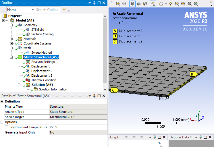
Let's apply that to a quarter model of a very thin sheet of glass (to make a mirror!) A rectangle of 0.5 mm thick glass is 80 mm long x 40 mm wide, but the model will be 40 mm x 20 mm long. The two cut faces that create the symmetry will each have a displacement support of 0 in the direction normal to the face. One vertex has a displacement support normal to the sheet of glass. Note that under the Mesh branch, a Method of Sweep has been used to get 4 elements through the thickness of the glass. The Element Order was set to Linear. Under the Structural branch, note that the Environment Temperature is 22 C.
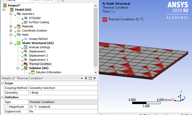
 Add a Thermal Condition of 23 C, which represents a 1 C temperature increase.
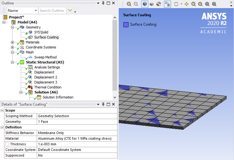
 Under the Geometry branch, Insert a Surface Coating. Pick the top surface of the solid body and fill out the Thickness of the coating, select the Material and set the Stiffness Behavior to Membrane Only.
 Now Solve the model and plot the deformation in the Y direction.
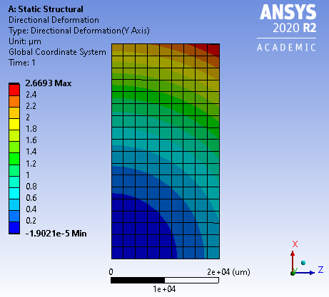 The 1 micron thick aluminum coating with a stress of 10 MPa has caused the pre-coated, perfectly flat 0.5 mm thick rectangle of glass to deform so the corner lifted 2.67 microns away from the flat plane.
You may think that is not exactly "scrolling up", but it's an example of a mirror, where 2.67 microns of deformation could be a big deal. If this was too much, then increasing the glass thickness to 1 mm will greatly reduce the deformation.
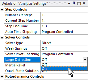
The above was a linear analysis, since the deformation was a small fraction of an element thickness. If you try this with a much larger coating stress to get a lot more curl, you will want to make it a nonlinear analysis. Under Analysis Settings, you will want Large Deflection turned On. My solution was accurate with that turned Off.
 December 18, 2021 at 4:35 pm
peteroznewman
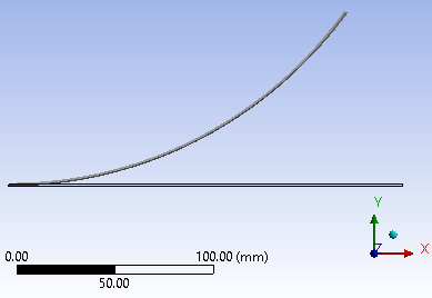
SubscriberMaking the coating stress much larger and making the length 200 mm long, a deformation that starts to look like it will scroll up becomes evident. The plot below is to True Scale. I mention that because on the Results tab is a display magnification scale factor. When small deformations are in the results, a display magnification factor of arbitrary size can be applied so that a deformation in microns become visible.

 December 18, 2021 at 9:49 pm
peteroznewman
SubscriberI couldn't easily get much more curl out of the solid element model shown above.
Back in SpaceClaim, I used a rectangular surface, 200 mm long, 20 mm wide.
In Mechanical, I defined a Layered Section and in the Worksheet, entered the material and thickness for the substrate and then the material and thickness for the coating. I switched over to using Symmetry Regions for the two cut edges.
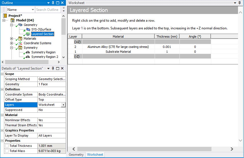 Now I can get 204 degrees of curl on the end. That means if I reflect the model about the symmetry plane to recover the full 400 mm long strip, it would have turned into a 109.75 mm diameter circle with 48 degrees of overlap of the two ends.
 Now that's what I call a scroll!
December 21, 2021 at 10:03 pmDor
SubscriberThank you very much for your answers!!!
First, I'm not sure why CTE is needed here for the simulation. Why the coating stress has any relation to the temperature? The scrolling caused by the stress in any temperature, no?
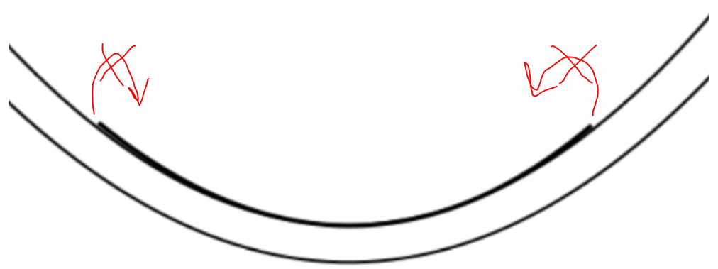
What if I want to do these simulations but not on a straight plane/table, but into a "bowl".
Like in this picture, where the black bold line is the paper, which tends to get the scrolling.

December 21, 2021 at 10:12 pmpeteroznewman
SubscriberThe CTE with the 1 degree temperature load is a trick used to create the coating stress. It has nothing to do with an actual temperature change. I mentioned that the substrate the coating is applied to has its real CTE set to 0 just for the purpose of causing the coating stress with the 1 degree temperature load.
The coating stress will begin to curl up a sheet that begins at any initial shape.
When you reply, put in your reply. That will make it easy for me to find your reply.
December 22, 2021 at 7:35 amDecember 22, 2021 at 2:15 pmpeteroznewman
SubscriberThe film center can curl into the bowl. If the coating is on the top, use a negative temperature change or a positive CTE and the direction of curl is reversed.
When the film center curls up, do you expect the edges of the film to be supported by the bowl and slide along the bowl as the curl increases?
Pressure is one of the load types you can apply to surfaces, you just select the surface and type in the value.
Is there a different pressure on the top of the film than the bottom of the film?
If so, how do the edges of the film seal against the bowl? If there is no seal, there can be no pressure differential.
If the bowl and film are surfaces of revolution, such as spherical, you could solve this problem as a 2D axisymmetric analysis, which will be easier and faster to solve.
December 22, 2021 at 6:16 pmDor
Subscriber
The coating is on the side that sits on the surface of the "bowl". The coating is type of a very elastic material, it causes the scorlling effect
I'd excpect that the curl will begin from the edges and not from the center of the film
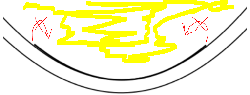
We can assume that the pressure of the yellow gas is constant.
I want to run this kind of simulations about different sizes and shapes of films, therefore not everytime it will be axisymmetric
December 22, 2021 at 6:36 pmpeteroznewman
SubscriberRegarding the question of a seal to keep the pressure from leaking around the edges of the film. Does the pressure push the soft elastic coating into the bowl? What is the coefficient of friction between the coating and bowl? As the film curls, how does air enter between the bowl and the film? Is there a hole to let air in?
The simplest model is to make the coating stress uniform over the entire surface. How much any part of the film curls is dependent on the shape of the film.
December 22, 2021 at 7:01 pmDor
SubscriberOK, I missed some more details that might be important: after the film is placed on the bottom of the bowl (when the coating is on the bottom side of the film too), the bowl is "closed" on its the top. We can assume that the pressure of the yellow gas which is stored into the bowl remains constant. Actually, the pressure is the reason that the film sits and remains there (on the surface of the bowl). However, the coating material is very elastic, which leads to the scrolling effect. We can assume the coating stress of the material is uniform and we can assume that some gas is enter to the space between the film and the bowl after the scrolling starts.
I don't know yet what is the coefficient of the friction, but I guess I can findfrom the scholarly literature, so lets assume I have the value (thinking about it now - the film and the bowl will have different values. Can I enter, while running the simulation, both of the those values as the properties of the materials?).
Sorry about my Ensligh (not my native language) and once again - thank you very much for answers!
December 22, 2021 at 7:58 pmpeteroznewman
SubscriberCoefficient of friction is a value measured between two specific materials, so is entered in the Frictional Contact Details window in the Outline in Mechanical.
Think about an elastomer suction cup you might have on a glass window or a glazed tile in the bathroom. Its natural shape is hollow on the contact side. When you push it against a smooth, non-porous surface like glass, the formerly hollow shape becomes flat and all the air is pushed out from between the suction cup and the glass. Atmospheric pressure pushes on the front side of the suction cup and it stays on the window for a very long time. If you peel it off, it returns to its hollow shape.
Your film and bowl sounds like the suction cup and window. The coating stress would have to be enormous to overcome the yellow gas pressure on the other side unless it is a low vacuum pressure, or if the surface of the bowl is rough and the gas can get behind the film.
December 22, 2021 at 9:02 pmDor
SubscriberI'm not sure if the analogy of suction cup and window is right, because the suction cup doesn't scroll, but I can agree with the general idea... we can assume ther's vacuum between the film and the bowl, and then there's a gas above the film with a const pressure. The film will remains on its place, but then because the elastic coating it scroll. The original shape of the film is circle. I want to run the simulations on different sizes and shapes of the film in order to study more about the behaviour of the scrolling and to find out if it can be prevented (or at least to try to reduce the its effects).
How would you do it on ANSYS? How would you create this kind of "bowl" in ANSYS?
December 22, 2021 at 10:55 pmpeteroznewman
SubscriberThere are two geometry editors available in ANSYS: DesignModeler and SpaceClaim. To make a bowl surface, draw an arc with the center on a coordinate axis, the start point on that axis, and make the end point at some distance from the axis. Revolve that arc around the axis to make a spherical surface. In SpaceClaim, that is done using the Pull tool. In DesignModeler, it is Create Revolve, select the sketch that has the arc in it and adjust the details to get a thin surface.
ANSYS has a wonderful ability to automate parametric testing. Below is one of my videos from a couple of years ago that shows how to make parameters in SpaceClaim. DesignModeler can also create parameters and is often more reliable because it is history-based geometry, while SpaceClaim is not. I recommend you work in DesignModeler.
If you lay out a table of each design parameter, and the range over which you want to study, that will make creating a parametric geometry model easier.
What is the radius of curvature of the bowl? What is the diameter of the film circle? What other shapes of film do you want besides a circle?
What version of ANSYS do you have? Attached is an ANSYS 2020 R2 archive with a parametric bowl done in DesignModeler. There are at least two choices for parameterizing the bowl, the horizontal distance to the edge of the bowl or the vertical distance. That is an example of the kind of planning that should go into the table. Which one do you want.
December 23, 2021 at 6:57 amDor
SubscriberThank you, I know the values of the radius of curvature of the bowl and the diameter of the film circle.
Other shapes, for example: ellipse and hexagon
For a very simple and general analytical calculation, can you help me find a forumula that shows the forces of the pressures and the stress on the film?
Or maybe a forumla that shows for which value of Young's modulus/gas pressure, the film will not move from its place.
I have the last student version.
December 23, 2021 at 1:51 pmpeteroznewman
SubscriberFormulas for layered materials are not simple. Formulas for shapes with curvature are not simple. That is the beauty of the Finite Element Method, you can use simple equations on each element, but then combine all the elements into a giant matrix and solve the simultaneous system of equations to get an answer to a complex structure with complex material properties.
For a specific modulus of film, coating, and a specific value of coating stress, there is a natural level of curl that develops with no other forces acting on the system. In the example below, that natural curl causes a 400 mm long x 20 mm wide flat strip to lift off the flat table by 73.8 mm.
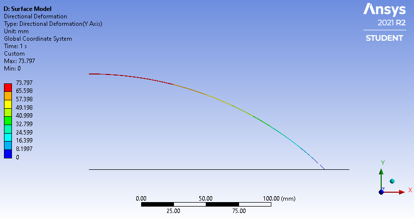 Search to find the Pressure that would keep the film from lifting off the table. 10 Pa is not enough as shown below.
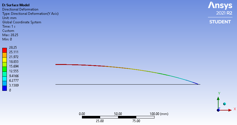 20 Pa is almost enough. Here you see the effect you were describing of the edge seeming to curl more than the center.
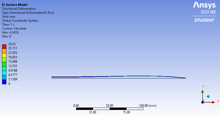
There is no table surface in this model for the film to push against, but if I added that to the model, I could increase the pressure so that the center of the film touched the table, but some of the strip near the edge would still have lifted off the table. If I increased the pressure more, I could ensure that none of the strip was lifting off the table.
Note that if the film was pressed flat against a smooth, non-porous table, so there was no air behind the film, air pressure of 101325 Pa would be pressing it against the table. That is what I meant by needing a very strong vacuum so the film curl could lift off the table. The vacuum pressure would have to be 20 Pa for the lift off to happen.
December 23, 2021 at 2:16 pmDor
SubscriberDo you think that there's no a simple equation which can describe the total forces on the film? Just in order to get some intuition, like a F.B.D, to calculate the general forces, shouldn't be very accurate (as you wrote, for more accurate work we need to use ANSYS)...
December 23, 2021 at 2:36 pmpeteroznewman
SubscriberYes, the simple formula is
F = P*A
where F is the total normal force, P is the pressure and A is the area with units as F in N, P in Pa and A in m^2.
But this doesn't work on a highly curved surface.
December 28, 2021 at 12:06 pmDor
SubscriberHi
I'm trying to put film shaped circle disk on the model of the bowel you attached here and to run the simulations only on the film. How can I do that?
And if I want to do the simulation "by timeline"? for example, to stimulate that the pressure will change every 2 days, how can I see what will be the result after 5 days?
December 28, 2021 at 12:27 pmpeteroznewman
SubscriberIf you want to simulate just the film without any bowl, use the surface created in the example I provided for the bowl and assign film material properties to it.
Use a Static Structural model to simulate the change in pressure. If you don't have any material creep properties in your model, then time is not real, it is just a way to meter out changes in loads. Therefore, you can ramp the pressure up to one value in 1 second, and change it to another value that ends at time = 2 seconds.
But it sounds like you expect something to change as it sits there, which implies you want to model creep. For that you need creep properties to be added to the material in Engineering Data. Once you do that, time becomes real in Static Structural and to simulate 5 days, you set an end time of 5*24*60*60 = 432,000 seconds.
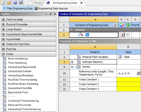 There are many creep models that you can read about in ANSYS Help under the Mechanical APDL, Material Reference manual.
December 28, 2021 at 2:38 pmDor
SubscriberWe have a bowl model in SpaceClaim but we want to move the DesignModeler, however in the DM it opens nothing...
December 28, 2021 at 3:17 pmpeteroznewman
SubscriberDecember 28, 2021 at 3:31 pmDor
SubscriberI've attached a .rar file. Both bowls in this .rar file are actually the same. One is just thicker and the thickness of the bowls is not important at all. So it doesn't matter which one of them will be in use. The inner part is the important because this is where the film should be placed (and I wrote, they are the same)..
Can you show me please how to make an assembly of the bowl (one of them) and a circle disk film? I'm just having many difficulties
December 28, 2021 at 3:33 pmDor
SubscriberSorry, the file is here (I don't know why its not showing on the last reply)
Imported from SolidWorks
December 28, 2021 at 3:50 pmpeteroznewman
SubscriberThanks!
December 28, 2021 at 4:04 pmDor
Subscriber
Thanks!
December 28, 2021 at 4:06 pmpeteroznewman
SubscriberThanks.
Viewing 28 reply threads- The topic ‘Scrolled Paper’ is closed to new replies.
Innovation SpaceTrending discussionsTop Contributors-
4618
-
1530
-
1386
-
1210
-
1021
Top Rated Tags© 2025 Copyright ANSYS, Inc. All rights reserved.
Ansys does not support the usage of unauthorized Ansys software. Please visit www.ansys.com to obtain an official distribution.
-
The Ansys Learning Forum is a public forum. You are prohibited from providing (i) information that is confidential to You, your employer, or any third party, (ii) Personal Data or individually identifiable health information, (iii) any information that is U.S. Government Classified, Controlled Unclassified Information, International Traffic in Arms Regulators (ITAR) or Export Administration Regulators (EAR) controlled or otherwise have been determined by the United States Government or by a foreign government to require protection against unauthorized disclosure for reasons of national security, or (iv) topics or information restricted by the People's Republic of China data protection and privacy laws.

