-
-
September 14, 2019 at 12:12 pm
Prashank
Subscriber
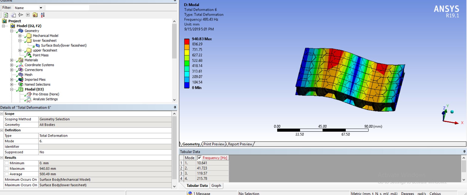
I am trying to simulate the standard ASTM 393 flat compression test on a composite panel with honeycomb structure at its core.
I modelled the facesheets in two ACPs and honeycomb geometry in design modular. For meshing i used quad dominant method ( SHELL   181 i guess) and for facesheets i used automatic meshing(solid 181 i guess). After importing these geometries in the static structure i do defined the contact - bonded between the honeycomb and facesheets.
Â
To simulate the test i fixed the lower face and then applied a remote displacement on the upper face (0.5mm/min).
Then i used stress probe to find out the compressive stress in the core, force reaction on the lower face sheet & stress probe in the upper facesheet.
The compressive strength of core is minimum and i assumed the sandwich will fail when the compressive stress in the core reaches the compressive strength.Â
the bare compressive strength of the core as given by the manufacturer is 2.85 MPa . And i was expecting compressive strength for the whole sandwich is greater than the sole core . But the results doesn't validated that.
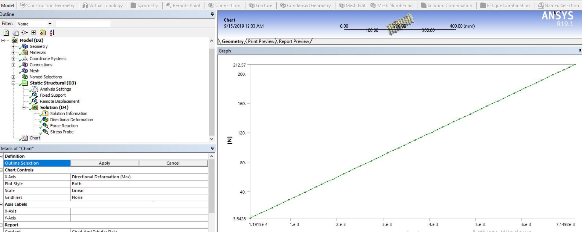
results obtained:
The compressive stress in the core is about 3 Mpa at 1.25 sec , so it fails before that.
The force reaction in the lower face sheet at 1.25 sec is about 330 N. Dividing it by the surface area of the facesheet (50X105) will give the compressive strength of the whole sandwich panel=0.058 Mpa.Â
So why is the compressive strength of panel is less than core?
Is there any mistake in my meshing, constraints ,method or the values i used to define the honeycomb core under orthotropic materiel is wrong?
-
September 14, 2019 at 4:29 pm
peteroznewman
SubscriberI recommend the first model be made of the honeycomb core only with no face sheets.
Pick all the edges on the bottom side of the core for Fixed Support. That represents a rigid face sheet.
Pick all the edges on the top side of the core for a Displacement of 0, 0, 2 and a Fixed Rotation 0, 0, 0.
This represents a rigid face sheet that moves in Z by 2 mm.
Request a Reaction Force in the results. This perfect geometry will have the highest buckling force. For a more realistic buckling force, you need to displace the perfect geometry by adding a small fraction of a modal shape.
Note that you will need a fairly fine mesh to allow the model to create local buckling. This is also very challenging to keep the solver converging all the way to the buckling point.
Please reply with the Force-Displacement plot. You need to see the plot become horizontal and go into a negative slope to be able to say that the core failed by crushing. You need to keep the Auto Time Stepping minimum number of substeps to a fairly high number to accomplish this. You also need plasticity in the Aluminum material model do allow this to happen.
-
September 14, 2019 at 7:13 pm
Prashank
SubscriberHi peteroznewman
I am using kevlar for honeycomb core , so i only have 9 orthotropic values . Can i define plasticity with only these values? and how?
i did what you suggested.
 My mesh size is 0.9mm, minimum no. of substeps = 60.
 Still this compressive strenngth is lesser than the core itself.
Â
Â
Is the model you are suggesting will be able to simulate the contact between the face sheets and core?
-
September 15, 2019 at 3:04 am
peteroznewman
SubscriberNo, you can't define plasticity with 9 orthotropic values of elasticity. It's in a different category.
I know how aluminum fails and that is why I mentioned plasticity. I don't know how kevlar fails.
If you have no failure law in the material model, compressing perfect geometry is uninteresting.
You need to add the appropriate failure law for kevlar into the material model and introduce imperfections into the geometry using a small fraction of some mode shapes. There are discussions on this site on how to do the geometry imperfection. Try the Search function.
The model I describe above is to study core failure, but only after you have introduced the items in the previous sentence.Â
Â
-
September 15, 2019 at 11:54 am
Prashank
SubscriberHi peteroznewman
I cant define any failure law for kevlar. My plan is to find the force at which the compressive stress(in core) is equal compressive strength of core and hence that force divided by area is the compressive strength of the sandwich.
i did find 6 mode shapes by point mass, cantilever method. And then i transferred the results of the modal to static structure for compressive testing. But the results doesn't change.
-
- The topic ‘sandwich composite panel’ is closed to new replies.
-
3190
-
1025
-
962
-
859
-
798
© 2025 Copyright ANSYS, Inc. All rights reserved.