I try multiple ways but it did not work.
This UDF works. but still there is some issue with translation of the wing zongs in the circular path.
#include "udf.h"
#define FLAPPING_FREQUENCY 1.0
#define FLAPPING_AMPLITUDE 30.0
#define CIRCULAR_RADIUS_Wing1 1.47995 // radius in meters for circular motion
#define CIRCULAR_RADIUS_Wing2 0.83819 // radius in meters for circular motion
#define CIRCULAR_FREQUENCY 0.5 // frequency for circular motion (Hz)
// First CG Motion function for Wing 1
DEFINE_CG_MOTION(flapping_wing_1, dt, vel, omega, time, dtime)
{
real angular_frequency_flapping;
real angular_frequency_circular;
angular_frequency_flapping = 2.0 * M_PI * FLAPPING_FREQUENCY;
angular_frequency_circular = 2.0 * M_PI * CIRCULAR_FREQUENCY;
// Time-based circular motion
real current_angle = angular_frequency_circular * time;
// Calculate tangential velocity for circular motion
real tangential_velocity = CIRCULAR_RADIUS_Wing1 * angular_frequency_circular;
// Only Y-direction movement (no Z movement)
// In UDF: vel[0]=Y, vel[1]=X, vel[2]=Z in ANSYS
vel[0] = 0.0;
vel[1] = tangential_velocity * cos(current_angle);
vel[2] = -tangential_velocity * sin(current_angle);
// Flapping angular velocity (around Y-axis in UDF = X-axis in ANSYS)
omega[0] = 0.0;
omega[1] = (FLAPPING_AMPLITUDE * M_PI / 180.0) * angular_frequency_flapping * cos(angular_frequency_flapping * time);
omega[2] = angular_frequency_circular;
Message0("Wing 1 - Time = %f, OmegaY(UDF)=X(ANSYS) = %f, VelY(ANSYS) = %f, Angle = %f\n",
time, omega[1], vel[0], current_angle * 180.0 / M_PI);
}
// Second CG Motion function for Wing 2
DEFINE_CG_MOTION(flapping_wing_2, dt, vel, omega, time, dtime)
{
real angular_frequency_flapping;
real angular_frequency_circular;
angular_frequency_flapping = 2.0 * M_PI * FLAPPING_FREQUENCY;
angular_frequency_circular = 2.0 * M_PI * CIRCULAR_FREQUENCY;
// Time-based circular motion with 180° phase difference
real current_angle = angular_frequency_circular * time + M_PI;
// Calculate tangential velocity for circular motion
real tangential_velocity = CIRCULAR_RADIUS_Wing2 * angular_frequency_circular;
// Only Y-direction movement (no Z movement)
// In UDF: vel[0]=Y, vel[1]=X, vel[2]=Z in ANSYS
vel[0] = 0.0;
vel[1] = -tangential_velocity * cos(current_angle);
vel[2] = -tangential_velocity * sin(current_angle);
// Flapping angular velocity (around Y-axis in UDF = X-axis in ANSYS) - opposite direction
omega[0] = 0.0;
omega[1] = -(FLAPPING_AMPLITUDE * M_PI / 180.0) * angular_frequency_flapping * cos(angular_frequency_flapping * time);
omega[2] = angular_frequency_circular;
Message0("Wing 2 - Time = %f, OmegaY(UDF)=X(ANSYS) = %f, VelY(ANSYS) = %f, Angle = %f\n",
time, omega[1], vel[0], current_angle * 180.0 / M_PI);
}
Second Method:
I also try to use the DEFINE_ZONE_MOTION.
But it does not work in my case.
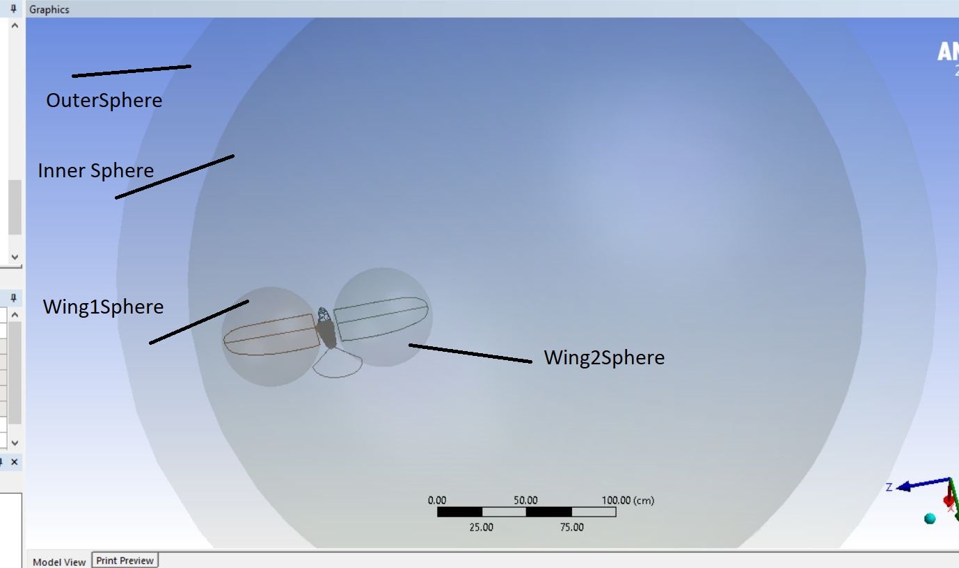
In this case i enable the rotation innerSphere Zone and it is working perfectly. But when I enabled the flapping Using this UDF. The WIngSphere Zone Does not flap. I do not know why. I enabled this UDF in CELL ZONE and set the rotation of the wingsZone relative to the inner Sphere. Here is the UDF for the Flapping. This is the good Option, but i do not know.. why it is not working.
#include "udf.h"
#define FLAPPING_FREQUENCY 1.0
#define FLAPPING_AMPLITUDE 30.0
// First Zone Motion function for Wing 1
DEFINE_ZONE_MOTION(flapping_wing_1, omega, axis, origin, velocity, time, dtime)
{
real angular_frequency_flapping;
real angular_velocity;
angular_frequency_flapping = 2.0 * M_PI * FLAPPING_FREQUENCY;
// Calculate angular velocity for flapping motion
angular_velocity = (FLAPPING_AMPLITUDE * M_PI / 180.0)* cos(angular_frequency_flapping * time);
// Set angular velocity components
omega[0] = 0.0; // No rotation around X-axis
omega[1] = angular_velocity; // Rotation around Y-axis
omega[2] = 0.0; // No rotation around Z-axis
// Set rotation axis (Y-axis for flapping)
axis[0] = 0.0;
axis[1] = 1.0;
axis[2] = 0.0;
// Set origin point for rotation (adjust this to your wing's pivot point)
origin[0] = 4.485e-005;
origin[1] = 5.0055;
origin[2] = 7.3644;
// Set translational velocity (zero for pure rotation)
velocity[0] = 0.0;
velocity[1] = 0.0;
velocity[2] = 0.0;
Message0("Wing 1 - Time = %f, OmegaY = %f\n", time, omega[1]);
}
// Second Zone Motion function for Wing 2
DEFINE_ZONE_MOTION(flapping_wing_2, omega, axis, origin, velocity, time, dtime)
{
real angular_frequency_flapping;
real angular_velocity;
angular_frequency_flapping = 2.0 * M_PI * FLAPPING_FREQUENCY;
// Calculate angular velocity for flapping motion (negative for opposite direction)
angular_velocity = -(FLAPPING_AMPLITUDE * M_PI / 180.0) * cos(angular_frequency_flapping * time);
// Set angular velocity components
omega[0] = 0.0; // No rotation around X-axis
omega[1] = angular_velocity; // Rotation around Y-axis
omega[2] = 0.0; // No rotation around Z-axis
// Set rotation axis (Y-axis for flapping)
axis[0] = 0.0;
axis[1] = 1.0;
axis[2] = 0.0;
// Set origin point for rotation (adjust this to your wing's pivot point)
origin[0] = -3.2794e-005;
origin[1] = 5.1117;
origin[2] = -5.196;
// Set translational velocity (zero for pure rotation)
velocity[0] = 0.0;
velocity[1] = 0.0;
velocity[2] = 0.0;
Message0("Wing 2 - Time = %f, OmegaY = %f\n", time, omega[1]);
}