(Rolling) Sheet thickness after rolling doesn’t match the roller’s gap
-
-
April 22, 2024 at 9:41 am
sgkcompany
SubscriberHi I simulate the rolling operation in static structural with 2 work roll, 2 back roll and a sheet.
Here is the size of each geometry.
Work roll
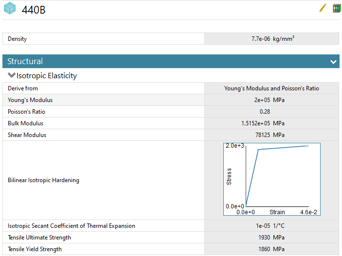
diameter: 100mm, length: 160mm, material: 440B
Back roll
diameter: 150mm, length: 160mm, material: D2
Sheet
width: 150mm, length: 100mm, thickness: 3.8mm rolls to 3mm, material: 316
Friction coefficient is 0.42, turn on large deflection, turn off autosubstep and set 500 substeps.
Use normal lagrange to minimize the mesh penetration and contact tool also shows no penetration.
Roller rotate 100 degree and sheet goes through roller with friction. (Didn't give sheet any displacement to help go through roller)
In sheet's symmetry plane I set the frictionless support.
The problem is sheet after rolling, the thickness deformation only shows -0.26 ~ -0.28mm in average.
I'm using symmetry so half the y deformation from upper sheet face should be -0.4mm (Roller's gap is 3mm and ignore material rebound since it's consider very small).
I also notice roller will shaking while rolling.
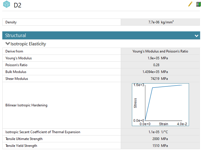
Material (All of them have plastic curve)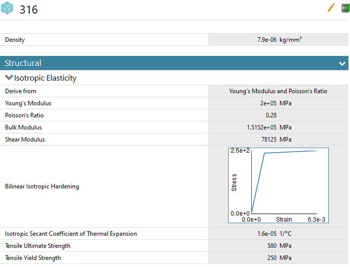
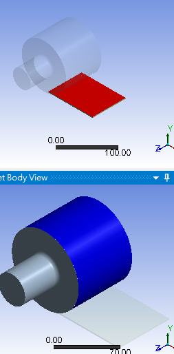
Contact setting (Frictional, Normal lagrange, Friction coefficient is 0.42, add offset; no ramping)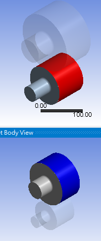
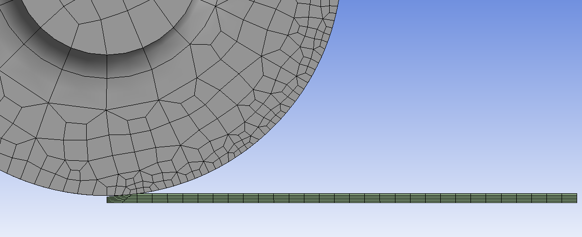
Mesh (Mesh metric shows average high quality)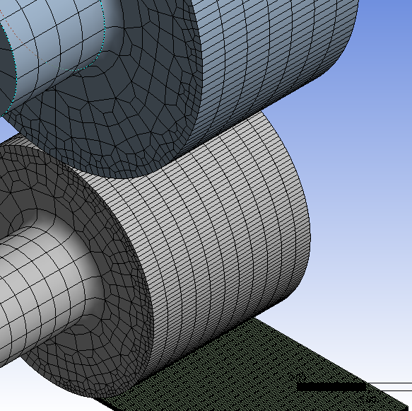
Joint (Revolute body to ground, Both back roll and work roll have this, and I set deformable instead of rigid)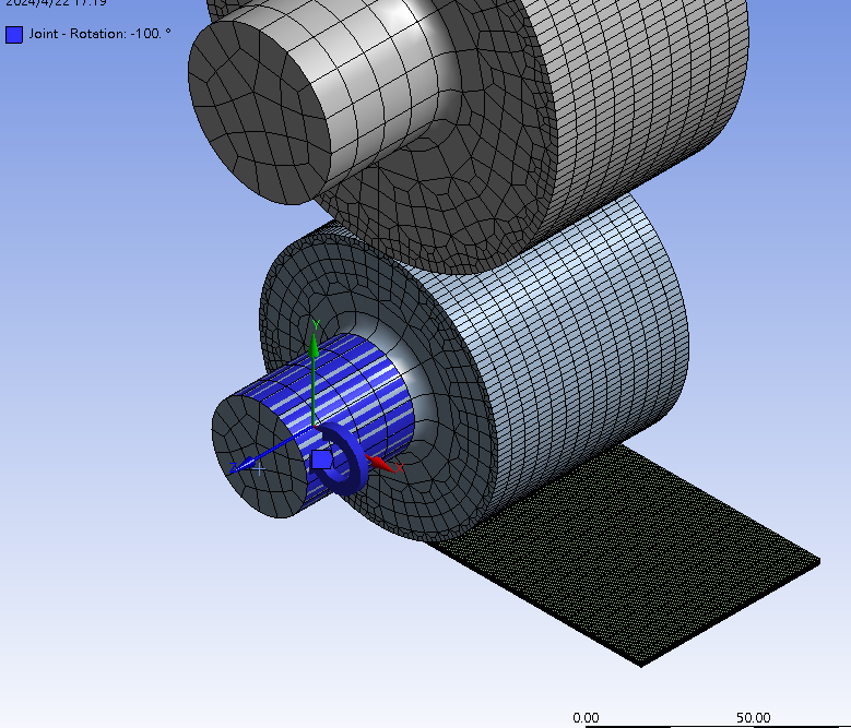
Solution setting (500 substeps, turn on large deflection)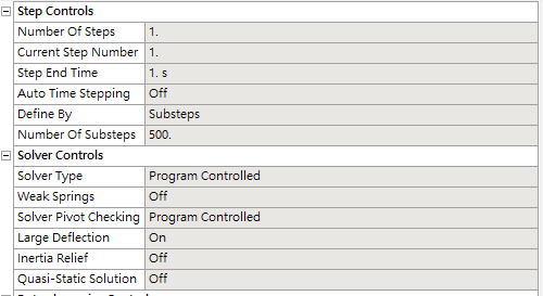
Result (Y Directional deformation should be very close to -0.4mm but only shows -0.26 ~ -0.28mm in average)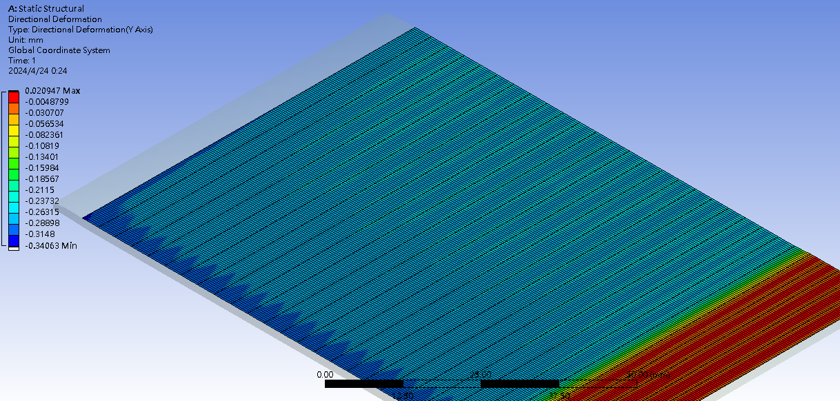
Roller shaking while rolling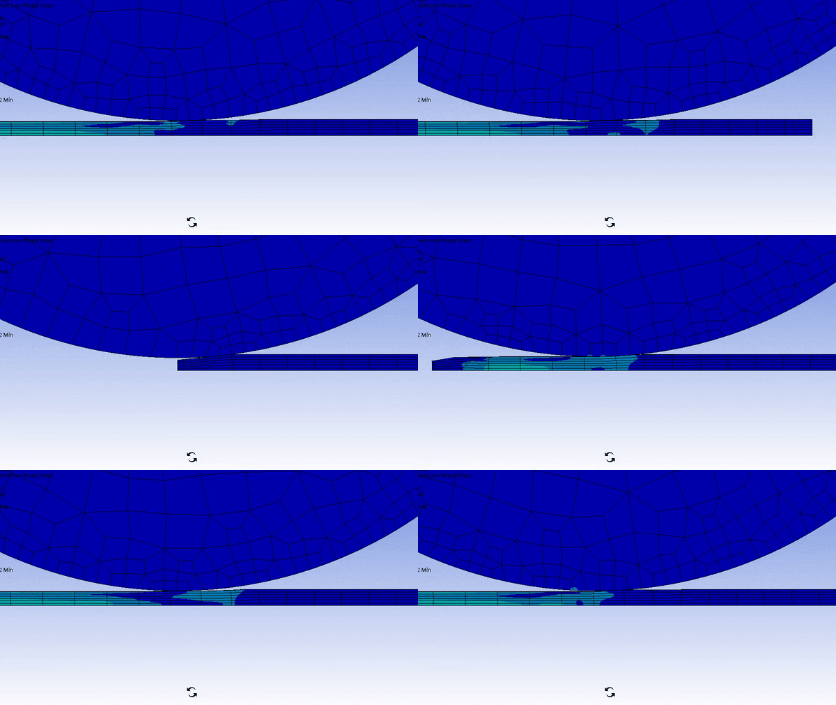
If anyone have solution I will be super grateful. -
April 25, 2024 at 2:45 am
mjmiddle
Ansys EmployeeYour deformation shows a max of 0.34mm on the revolute ground mount side of the rollers, and the other side looks about 0.26-0.29mm. It seems to be the purpose is to flatten and extrude the sheet (it should expand in the directions parallel to the sheet), so you would want a material that is a lot less stiff than the rollers or at least yields at much lower value. These 3 materials are fairly close in stiffness. Material 316 does have a lower yield strength. Have you checked if any of these materials are yielding? Do you have any other constraints on the sheet other than the symmetry or frictionless support? It seems to me in this process, you would want the sheet to yield but not the rollers.
Contact "target" side should be the flat plate, and contact "contact" side should be the convex surface, which is the wheel. Your image looks reversed in that regard.
Have you tried a penalty based contact, such as augmented lagrange, where you can adjust the normal stiffness factor?
Why are two rollers needed? This seems like an extrusion type of operation, and I would think you only need the one roller touching the plate.
It is true that a roller model will need very small element size on the wheel, and yours does look pretty small. But you could try even smaller to see how that affects the bouncing.
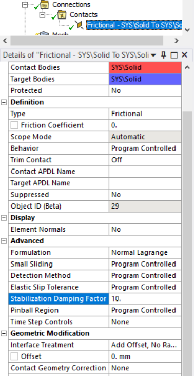
Set trim contact and small sliding to off.
Try a nonzero factor for "Stabilization Damping Factor" on the contact:
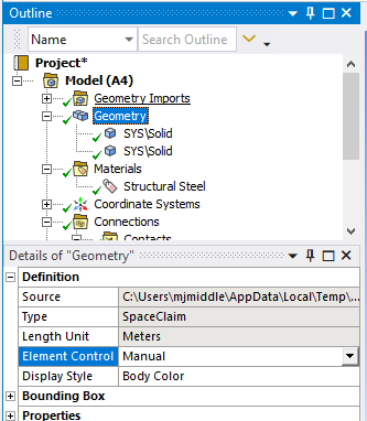
You may want to reduce the joint tolerance with an APDL command to allows less joint "chatter" within that distance. This may require smaller time stepping.
Undocumented JTOL argument:
SOLCONTROL, Key1, Key2, Key3, VTOL, JTOL Where, JTOL is used to specify the tolerance.
Currently the tolerance is set to: 1.E-07 ( an absolute tolerance value). -
April 25, 2024 at 2:49 am
-
April 25, 2024 at 1:08 pm
sgkcompany
SubscriberThank you for taking the time to reply.
Only sheet are yielding, both roller doesn't have plastic strain.
Sheet only have frictionless support.
After switch contact and target, should I make roll's mesh smaller than sheet? (since contact should have smaller mesh than target)
When I use augmented lagrange, I always get an error, since like I don't know how how to set a correct stiffness factor. (I use 10 in work roll to sheet, 1 in back roll to work roll, also set 0.01 penetration tolerance)
The reason I use back roll is my project is to obverse how different shape of backroll affect sheet's surface shape. (Can't get rid of back roll)
If I have two contact setting like work roll, back roll and sheet. Is my setting correct?
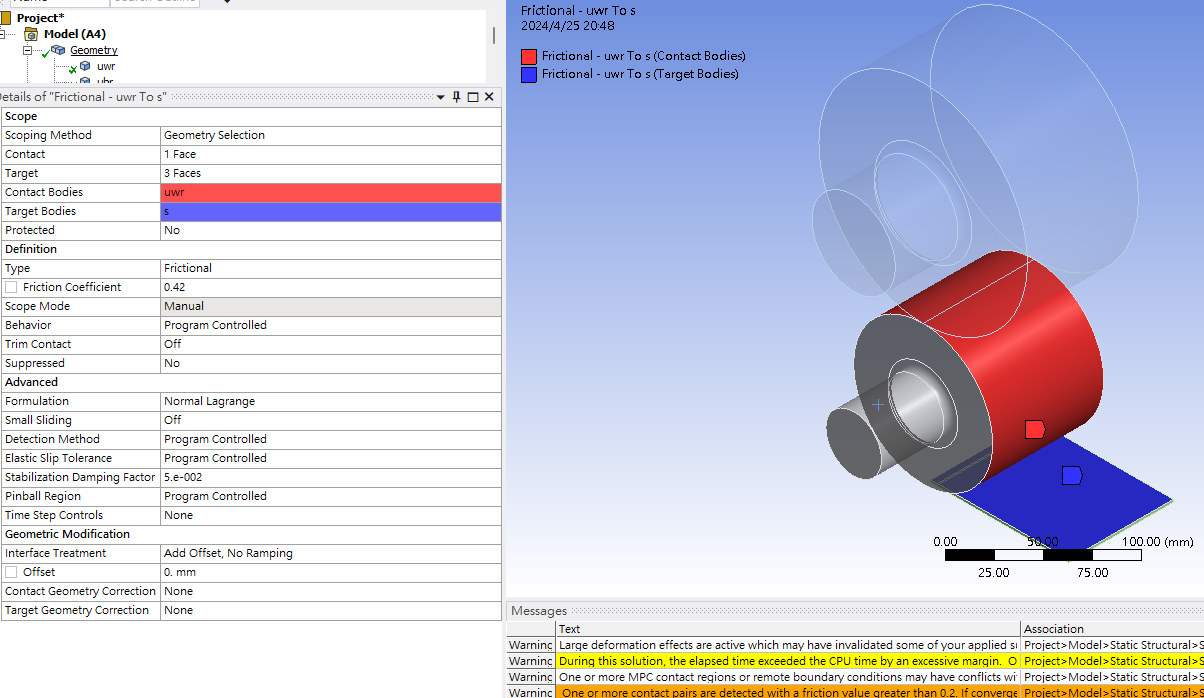
Joint tolerance default value is 1e-7, I think is already small ,it should not chatting so much or I just misunderstood the value?
After trying mesh solution, changing contact and target side, turn off trim contact and small sliding and I add a 0.05 stabilization damping factor.
Here is the result (I make mesh bigger to speed up the process)
The side of sheet's deformation looks more consistent, which I think is good, but the y deformation still remain the same.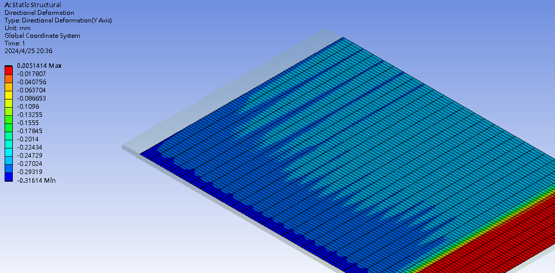
Mesh penetration (contact tool shows no penetration or very small like 0.0003 max, is this just graphic problem?)
You can see rolls mesh penetrate the sheet a little.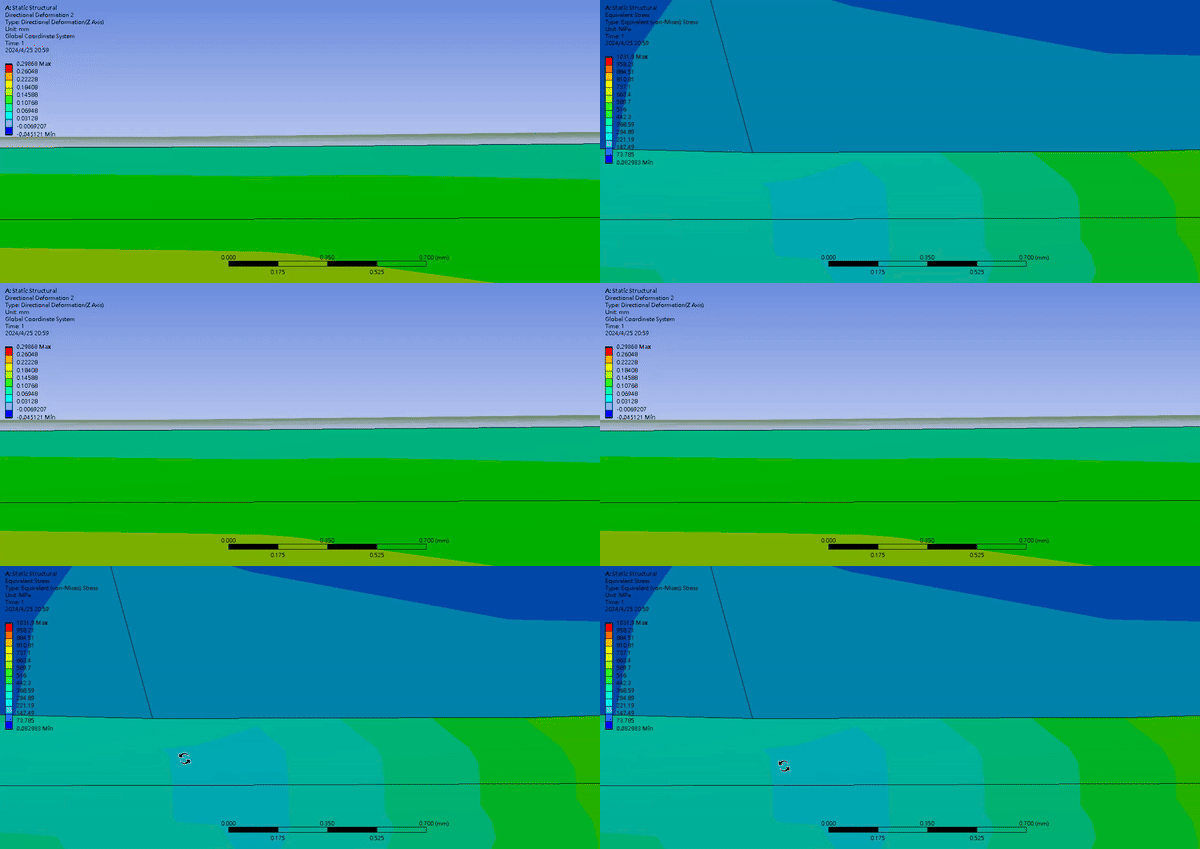
-
April 26, 2024 at 6:22 am
mjmiddle
Ansys EmployeeRoller-to-roller contact probably doesn't need stabilization, and since the rollers are not very different diameter, it wouldn't matter which side is target side. But the roller-to-plate is more important for stabilization and "contact" side selection, which should be the roller. Yes, it should be able to work with smaller mesh on contact side than target side, especially on a flat target. But contacts in general work best with similar sizes on both sides. Since you are debugging a problem, it would make sense to test the effect of similar mesh sizes on both sides.
Don't mix frictionless support and symmetry on the same face. Use one or the other but not both. A frictionless support on a flat face should set up the same constraints as a mirror symmetry on that face.
If you have switched to augmented lagrange contact (or pure penalty), you should know that penalty based contact works by accepting some penetration. If there is no penetration, a contact tool result will report zero pressure and a non-touching contact status. For that reason, the normal lagrange is probably a good choice for this model, when normal contact deformation direction is critical for the correct plate deformation, but it's reasonable to see how that contact type behaved. Did it get rid of the bouncing? For penalty based contacts, you can adjust the normal stiffness factor to see if that helps. Instead of relying on the close up visual deformation result to detect penetration, use a penetration result under a contact tool. Also, stabilization factor of 0.05 is very small. Try larger numbers first such as 10 or even 100. If it gets rid of the bouncing and makes the plate deform larger, than reduce the stabilization factor to the point where the roller starts bouncing again. Then adjust to a value just above that.
Also, to reduce the bouncing, try defining two contacts on the wheel and plate with the same contact/target side selectons. But make one with detection method set to "on gauss point", which is the program controlled choice for 3D models using face contacts. On the other contact, use a nodal detection scheme, such as "normal from contact" or "normal to target." The "projected normal from contact" is also worth trying.
If none of this works, maybe you need a better material model for the plate, such as a multilinear isotropic hardening property. I would be more convinced this is necessary if everything else in the model appeared to be working correctly, such as if you can get rid of that roller bouncing.
-
April 26, 2024 at 2:34 pm
sgkcompany
SubscriberThank you for helping.
What do you mean ''try defining two contacts on the wheel and plate with the same contact/target side selectons'', you mean I can have a plane have both contact and target side?
Roll to roll use ''gauss point'' or ''normal from contact''? But normal lagrange can't use gauss point. Can you give me more info about it. -
April 26, 2024 at 2:43 pm
mjmiddle
Ansys EmployeeNo I mean define 2 contacts for the roll-to-plate with the same contact and target face selections, not flipped.
I forgot normal lagrange doesn't have gauss point. I had only tried the strategy before with penalty based contact. You could make an augmented lagrange contact with gauss point in addition to your lagrange, but it it may not help in that case. Try the higher contact stabilization value. Or maybe add some damping with a body-to-ground spring on the roller axle, and only specify damping coefficient. It seems to me the real issue is probably the material properties.
-
April 26, 2024 at 4:07 pm
sgkcompany
SubscriberSorry I still get little confused
here is my current setting
1 for roll to roll back roll is target ; work roll is contact
2 for roll to plane work roll is contact ; sheet is target
You said I need 2 contacts for roll to plate but I only need 1 there. -
April 27, 2024 at 7:08 pm
sgkcompany
SubscriberHello after I change stabilization damping factor to 25 the result are getting finer. (I tried 50 but get an error)
I also adjust material to let 316 less stiffness and make 440B and D2 more stiffness.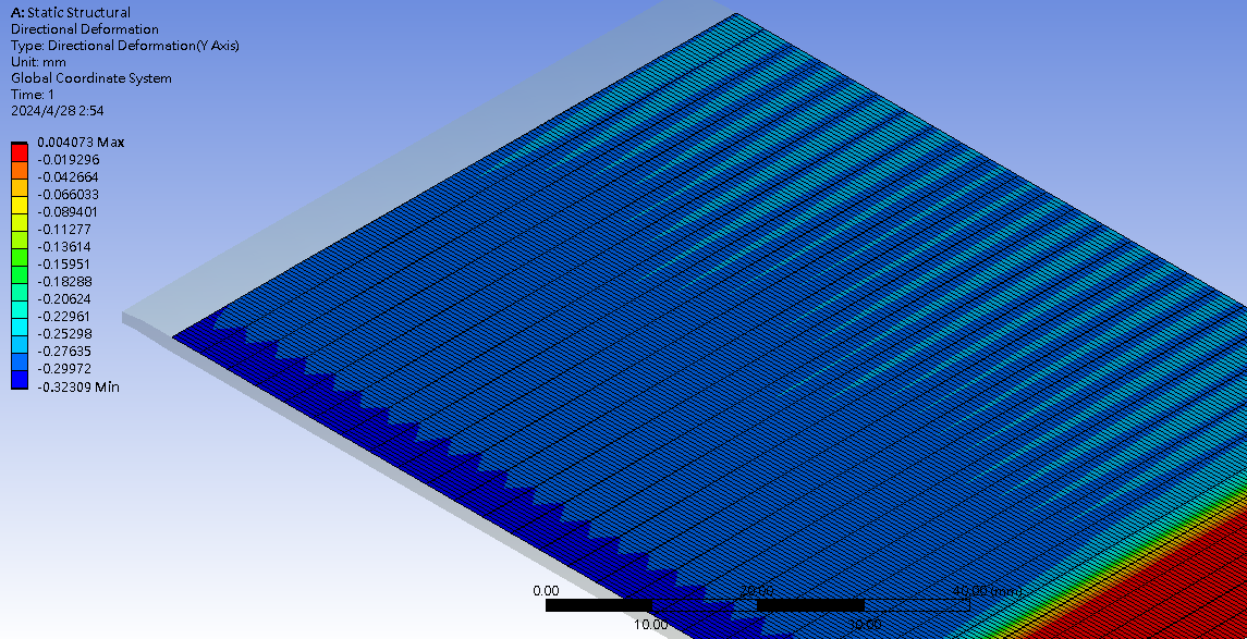
Bouncing problem still happened (But non contact area also deform when rolls goes up)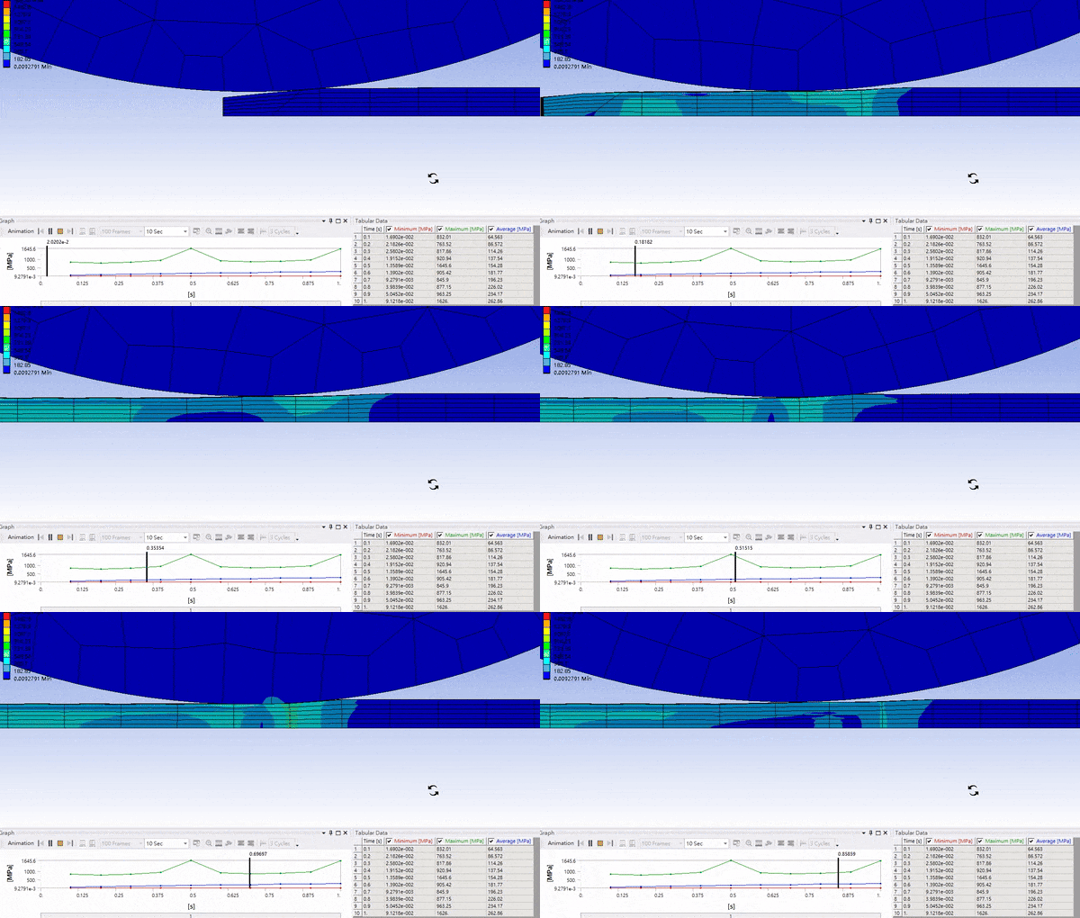
Contact tool (very small, using lagrange, result use equally space points so only 10 result)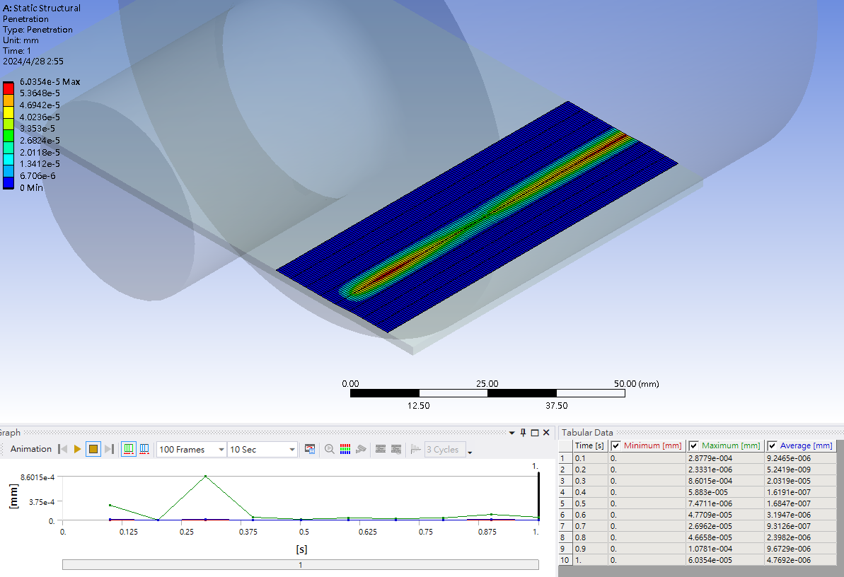
-
June 4, 2024 at 12:35 pm
sgkcompany
SubscriberI think the problem is roller will move a little up when plate go in, silly me never consider this.
Turn off trim contact and small sliding help the result more convincing, the deformation is more continuous than before. -
June 5, 2024 at 12:39 pm
mjmiddle
Ansys EmployeeDid you set any global damping? Also, newer versions of ansys have a "Combined" detection method setting so you dont need to make 2 sets of contacts: one with gaues and one with nodal detection.
-
- The topic ‘(Rolling) Sheet thickness after rolling doesn’t match the roller’s gap’ is closed to new replies.


-
4597
-
1500
-
1386
-
1209
-
1021

© 2025 Copyright ANSYS, Inc. All rights reserved.

