-
-
August 7, 2023 at 7:27 am
Paolo Langella
SubscriberGood morning everyone,
I'm trying to perform a static simulation to evaluate the stress in the wires that actuate a snake robot made of rolling joints.
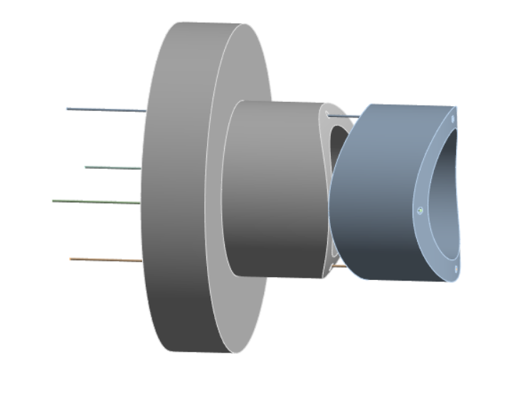
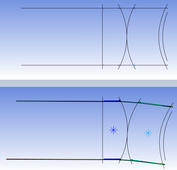
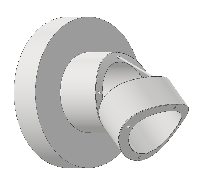
At the moment I am focusing on a model which is composed of a base, a link and 4 wires.
Since I am having convergence issues, I'd like to have some feedback about it.
The settings of the analysis are the following:
- Base and link bodies are rigid, while the wires are flexible.
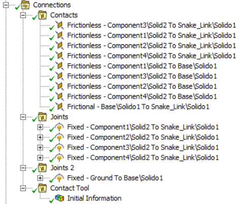
- Connections:
- Frictionless contact between the wires and the link and the wires and the base. Stabilization damping factor of 0,05 and time step control predict for impact;
- Frictional contact between the base and the link with friction coefficient of 0.2;
- Fixed joints on the right between the edges of the link and the wires;
- Ground to base fixed joint to the surface of the base on the left;
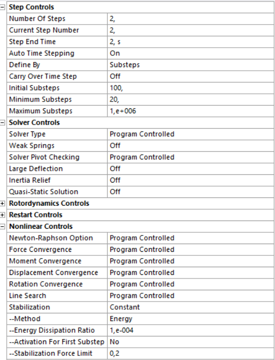
- Analysis settings
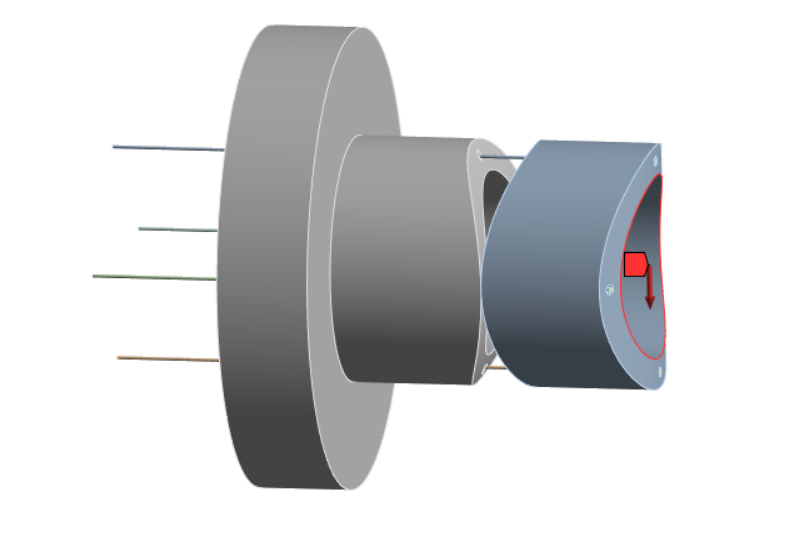
- Two wires are pulled while the other two have a fixed support constraint;
- Remote force on the edge of the link;
Thanks in advance to anyone that can help me.
-
August 7, 2023 at 7:45 am
Akshay Maniyar
Ansys EmployeeHi Paolo.
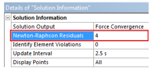
Convergence issues can be tricky. Can you share the error message you are getting? Also, it looks like you ran the model with a Large deflection aet to OFF. We generally recommend running the model with a large deflection option set to ON. Also, check for Newton-Raphson residuals. The Newton-Raphson Residual data (if requested) will show graphically which areas had the highest force residuals. These areas usually correlate with the phenomena that are preventing the achievement of force equilibrium (convergence).
Thank you,
Akshay Maniyar
-
August 7, 2023 at 7:59 am
Paolo Langella
SubscriberHello Akshay,
Thanks for your reply. I thought I selected large deflection on in both steps, but actually I noticed I didn't select it for the second step. Maybe this is the reason why I didn't get any error but after five days It still didn't converge. I'll try to run again the simulation.
If you have any other feedback it would be much appreciated.
Thank you for your time.
-
August 7, 2023 at 2:31 pm
peteroznewman
SubscriberPaulo,
For the surfaces that are rolling on each other, I suggest changing the contact from Frictionless to Rough.
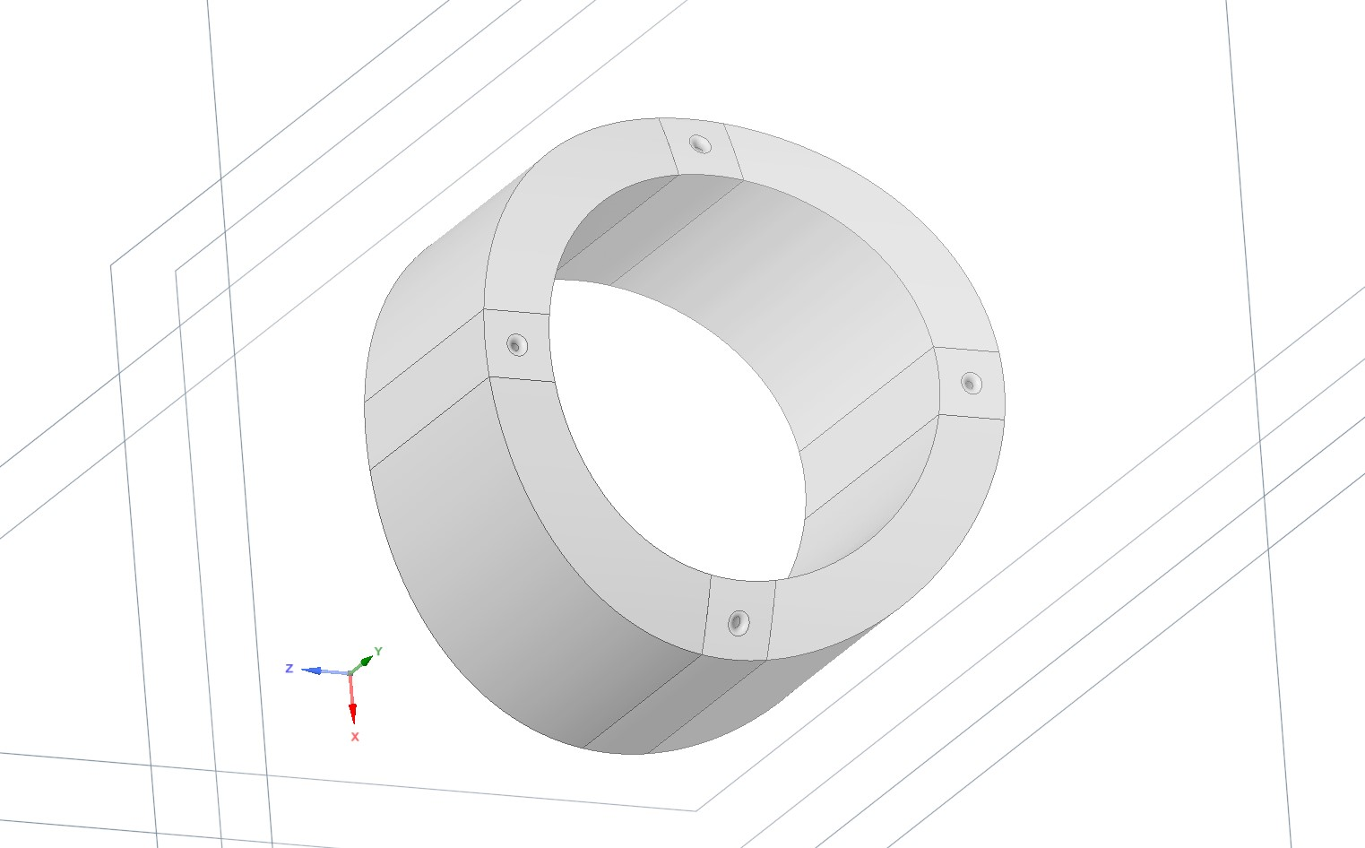
I suggest adding a blend radius on the edge of the hole in each rigid link. Add a sizing mesh control to that blend so there are several elements around the blend radius. Make sure the element size on the cable is small enough to put several elements in the size of the blend radius.
There are two cables, one on the top and one on the bottom. One cable should be attached to a spring to ground with a pretension on it. The other cable should have a displacement boundary condition to shorten or lengthen the cable to bend the snake up or down.
These three changes will make the model converge more easily.
-
August 9, 2023 at 6:41 am
Paolo Langella
SubscriberHello Peter,
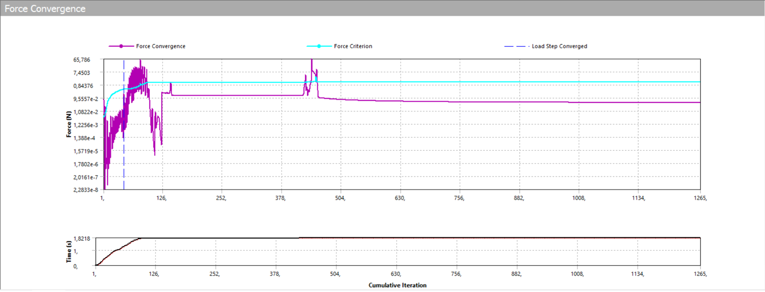
Thank you for your reply. I'm still having some issues with convergence but my doubt is why do I have a lot of substeps that converge but the solution doesn't? And also there is no error message.
Then, I was wondering if I could get a feedback about my model because my goal is to move to a more complex one with six links and the wires attached to the last link. I want to evaluate the force which is necessary to keep the robot straight in an orizontal position.
-
August 9, 2023 at 10:17 am
peteroznewman
SubscriberThe solution control logic has many convergence criteria besides the one you are plotting. For example, you can plot Displacement Convergence, or Moment Convergence (for some elements).
In Workbench, use File Archive to create a .wbpz file, and do not include results. Put that file (not the .wbpj file!) on a file share such as a Jumpshare, OneDrive or Google Drive (allow anyone with the link to download it). Put the link in your reply and I will download it and take a look. In your reply, say what version (Year and R#) of Ansys you are using.
-
August 9, 2023 at 2:58 pm
Paolo Langella
SubscriberHello Peter,
Thank you for your time, this is the link of my project and the analysis of interest is "Tendon solution - complex". Ansys 2022 R2.
https://drive.google.com/file/d/1-32n0Q9TotnPW-JgBVWBRfEQSA8zkupv/view?usp=sharing
Please let me know if mine is a good way to proceede since, as I wrote in my last reply, in the future we want to make the model more complex adding links, wanting to evaluate the stress in the wires and contact interactions during motion.
-
-
-
August 13, 2023 at 1:31 am
peteroznewman
SubscriberHello Paulo,
Cable operated joints are not easy models to get working. I modified your model significantly. In particular, I reduced the cable material Young's Modulus to make it stretch a lot and act like a spring. In a 3-step analysis, step 1 stretches the cables to the left by 10 mm to tension the system, then in step 2 and 3, the top cable returns to 4 mm left while the bottom cable continues on to 16 mm to the left, causing the joint to rotate down. The joint uses Rough contact so that the surfaces can only roll and cannot slide.
Here is the link to the Ansys 2022 R2 archive.
-
August 14, 2023 at 3:21 pm
Paolo Langella
SubscriberHello Peter,
Thank you for your help.
-
September 25, 2023 at 8:33 am
Paolo Langella
SubscriberHello Peter,
I would like to ask for your opinion.
The goal of my analysis is to analyse stress in the wires, the contact force between the rolling elements and the interaction between the wires and the holes.
- Do you think static structural analysis is the most appropriate one to choose, or should I move to transient or motion (even though I couldn't find any motion tutorial)?
- I did most of my analysis using solid elements, should I move to link180 or cable280 to model the wires?
- Should I just consider a set of static configurations and analyse them instead of applying variable loads?
-
-
September 25, 2023 at 7:55 pm
peteroznewman
SubscriberHello Paolo,
Static structural is the best analysis to use if the velocity is small so that inertia forces are small. When the inertia forces become significant, then you will need to use Transient Structural.
Cable280 elements are better elements to use for this application.
I don't know what you mean by the third bullet. Please explain each in detail.
-
September 26, 2023 at 11:50 am
Paolo Langella
SubscriberHello Peter,thanks for answering.I thought about using cable280 but I couldn't find any material about how to properly set the contact between the elements of the wires (cable280) and those of the holes (solid).Also, I would like some suggestions about how to obtain an high quality mesh. I thought about splitting the link with 4 planes, with a fine mesh around the holes and a more coarse one elsewhere, but I am having some issues because of the shape of the bodies.In the third point I mean that an alternative way of analyse the problem could be to chose a set of robot configurations and times es horizontal pose or an extreme pose and perform the analysis with a costant load instead of using a variable load to simulate the movement of the robot.
-
-
September 26, 2023 at 10:01 pm
peteroznewman
SubscriberYou should start with straight cables and operate the mechanism to reach the poses.
The problem with configuring the mechanism at an extreme pose is that you will draw the wires in the deformed shape. The simulation starts with no stress or strain in the wire. Drawing a bent wire is like taking a wire and putting a kink in it. As you operate the mechanism near that configuration, the kink will travel into or out of the hole and that is not a realistic representation of a real wire.
Use Rigid Bodies for the links. That way, you don't need to worry about meshing the solid, only the contacting surfaces and for those you can use a relatively fine mesh.
Cable280 elements will make contact with the holes in the rigid bodies in the same way that the beam elements do in the model I provided previously.
-
September 27, 2023 at 12:12 pm
Paolo Langella
SubscriberHello Peter,Thank you for your answer.In the past few weeks I did a model with rigid links and flexible wires modeled with solid elements, now my idea is to set the links to flexible in order to analyze the interaction between the wire and the hole (I couldn't find a way to have these informations with the rigid links model).We need this analysis because the links should be 3D printed (we chose sla technology to have almost isotropic parts that are easily simulated by ansys) and we want to check if the material used is good for our purposes.After your answer I did the same model with cable280 elememts for the wires.I attach both of them if you want to have a look (Ansys 2022R2).https://drive.google.com/file/d/1-Kf8_E6p4oUQx2cawoYvy9x_a3x6yX_l/view?usp=sharingThe next step would be to set a remote force to simulate the presence of the other 4 links and manipulate the wires in order to analyse the contact interactions link-link and link-wire.Any suggestions are much appreciated as always.
-
-
- The topic ‘Rolling joint model check’ is closed to new replies.


-
5069
-
1792
-
1387
-
1248
-
1021

© 2026 Copyright ANSYS, Inc. All rights reserved.

