TAGGED: ring-resonators, transmission
-
-
August 8, 2024 at 7:16 am
m.hoormann
SubscriberHello,
I tried to simulate a ring resonator adapted from the given example with varFDTD.
The calculated forward transmission at the end of the waveguide seems to be fine. However, inside the ring resonator transmission values of more than 1 are achieved. The transmission values also seem to increase with the simulation time.
Simulation times of 30000 and 100000 fs have been tried and the simulation status was 1. For the longest simulation time the oscillations have diminished significantly for the forward transmission into the end of the waveguide, but the transmission inside the ring resonator are still too big.
The standard PML boundaries have been used.
Could you recommend changes I could try, like increasing the PML layers? Or could the simulation time still be too small?Kind regards.
-
August 9, 2024 at 7:51 pm
anna.wirth-singh
Ansys EmployeeHello,
Resonators typically require a long simulation time to ensure that the energy in the simulation has sufficiently decayed; this is a common cause for transmission greater than 1 (Transmission Results Greater Than One – Ansys Optics).
However, I think the most likely cause of this issue is the placement of the port with anomalous results. Could you perhaps clarify where the port is placed to measure the transmission “inside the ring resonator”? If the port is placed on the ring itself, this could cause the high transmission value. To measure the outcoupled light, the port should be placed on one of the waveguides exiting the simulation region.
If this is not the issue, there could be an issue with the PML settings. If you have not already done so, a movie monitor can be helpful to check if the PML is not absorbing as it should. As a next step, you can try to make sure that the monitors are at least λ/2 away from the PML boundaries.
-
August 12, 2024 at 11:29 am
m.hoormann
SubscriberHello,
thank you for the answer.
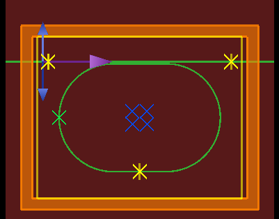
The port in the ring itself is positioned at the bottom and the port on the waveguide is placed at its end (see the picture).I found that increasing the simulation time further to 200000 fs and using 64 PML layers got rid of the issue. However, I would think there could be still an issue, as the simulation time seems unnecessary high.
-
-
August 13, 2024 at 9:21 pm
anna.wirth-singh
Ansys EmployeeThe port at the bottom of the ring itself is a bit unusual. Ports are typically placed on the input/output waveguides to the device, as you have them on the top waveguide, so I would recommend using the transmission results from the top two ports.
Nevertheless, I am glad that increasing the simulation time has resolved the issue. Since ring resonators can have a very high Q factor, very long simulations may be required in order for all the light to leave the simulation region, so the long simulation time is not too surprising. Another thing that you can try is to select the ‘stabilized’ PML profile option on the x-boundaries (see PML boundary conditions in FDTD and MODE – Ansys Optics). The stabilized PML option could be used at the x-boundaries where the waveguide intersects the boundary, while the standard PML boundaries can be used in the y-boundaries to try to reduce the simulation time. However, this is probably not necessary because there does not seem to be any indication of divergence here.
Additionally, we often recommend breaking up a large ring resonator like this into pieces and simulating the ring in INTERCONNECT, as shown in these examples:
https://optics.ansys.com/hc/en-us/articles/360042322794-Ring-Modulator
-
August 14, 2024 at 8:26 am
m.hoormann
SubscriberThank you again for the answers.
I will use the transmission from the port on the waveguide from now on.
-
-
- You must be logged in to reply to this topic.


-
5094
-
1823
-
1387
-
1248
-
1021

© 2026 Copyright ANSYS, Inc. All rights reserved.


