TAGGED: peteroznewman
-
-
November 10, 2021 at 9:24 pm
tumulpurwar
SubscriberDo we have any substitute for Rigid body element & Master Slave joints if FeMAP in Ansys workbench??
Thanks all
November 10, 2021 at 10:36 pmpeteroznewman
SubscriberPlease describe what you want to accomplish. ANSYS has many types of Joints that can be inserted under the Connections folder and the Scope can be set to Rigid or Deformable.
November 11, 2021 at 3:50 amtumulpurwar
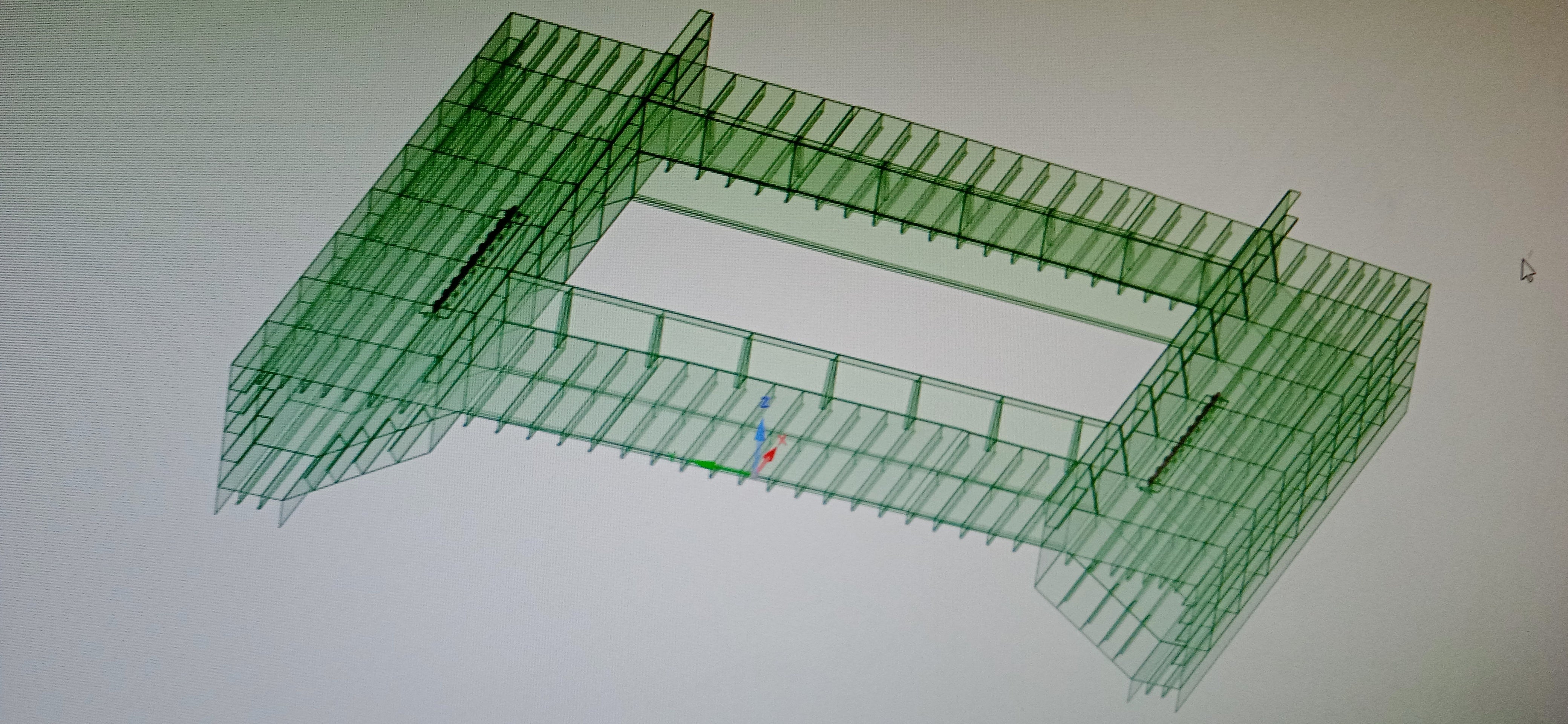
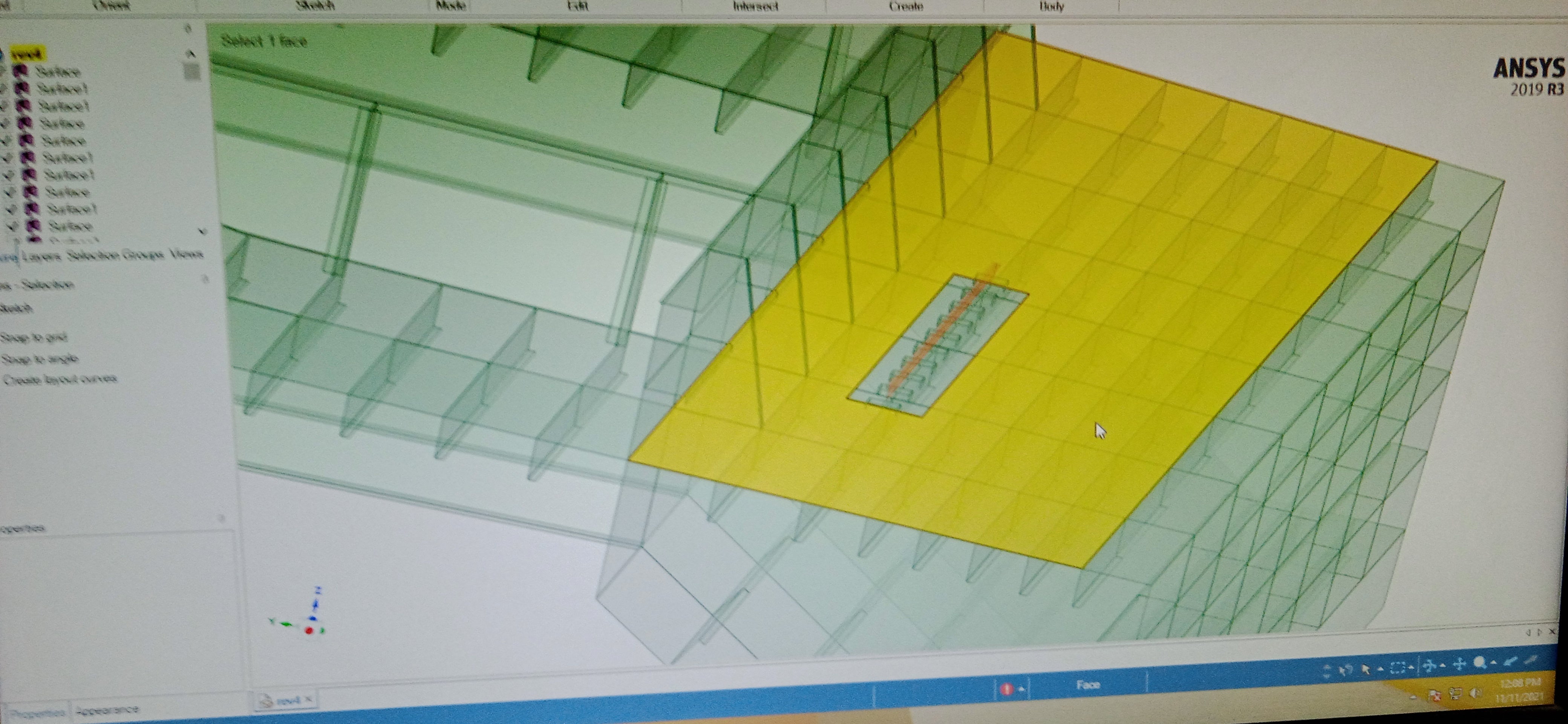
SubscriberI have tug vessel, where I am doing local analysis and I made 25 % part of vessel and want fix both end of vessel, fixing the translation but letting rotation free on both ends.
November 11, 2021 at 4:01 ampeteroznewman
SubscriberPlease insert an image to illustrate your model and boundary conditions.
You say you have a 1/4 model, which implies two planes of symmetry that take away all freedom of rotation. Only one DOF remains, which is along the intersection of the two planes.
November 11, 2021 at 4:04 amtumulpurwar
SubscriberI want use CERIG in workbench, is it possible?
November 11, 2021 at 4:10 ampeteroznewman
SubscriberYes, you can use CEIG in workbench, just set Joint Behavior to Rigid.
Where is the image of your model?
November 11, 2021 at 6:59 amNovember 12, 2021 at 3:17 amtumulpurwar
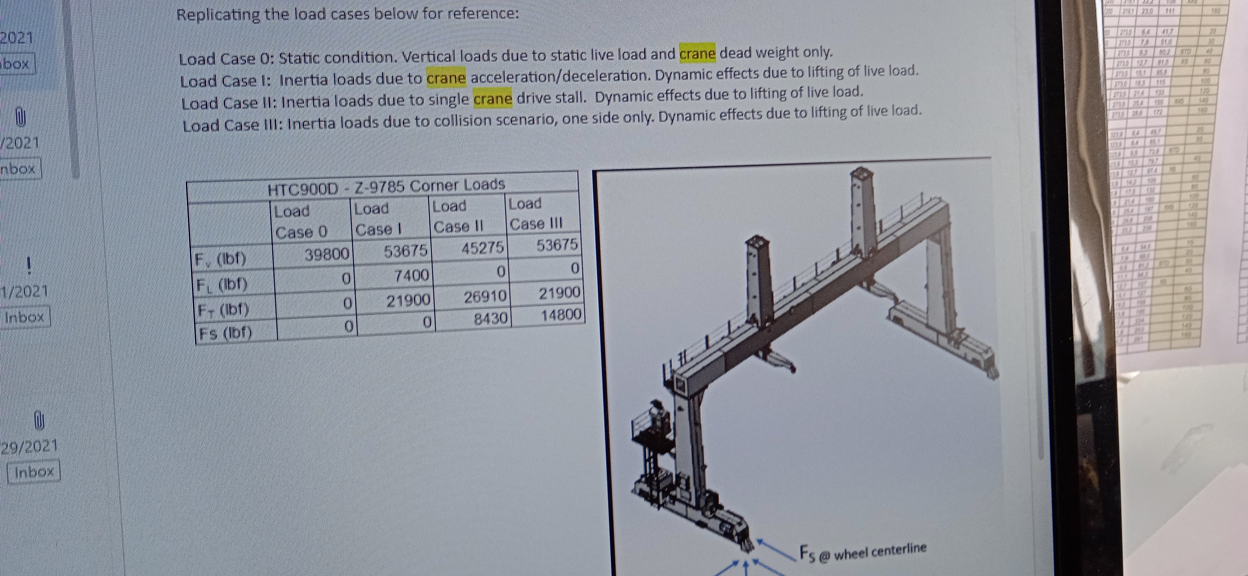
SubscriberSo these T girder are getting load from crane in 3 directions
Horizontal, Vertical(Weight of crane) and transverse.
I just want know boundary condition at both extreme end of vessel, I just made 25% of vessel, over where rail crane will move
November 12, 2021 at 3:22 amtumulpurwar
SubscriberOnly one dof remain which is along intersection of two symmetry plane,?
I didn't get it, which dof still remain??
I thought to fix both extreme ends of vessel, is it wrong?
November 12, 2021 at 12:08 pmtumulpurwar
SubscriberHello peteroznewman
Would you like answer? The boundary condition in this case?
Normally instead of fixing both extreme ends free edges, I will prefer rigid element, as the whole structure of ship is in shell element, and shell element doesnot support drilling rotation, so rigid will be correct option instead of fixing both extreme ends?
November 12, 2021 at 2:47 pmpeteroznewman
SubscriberI see from the images that the two planes that cut out 1/4 of the tug are parallel. I guessed that the two planes were 90 degrees apart, in which case, there is only 1 DOF along the intersection of the two planes. That doesn't apply to two parallel planes.
You can put a Remote Displacement scoped to all the edges on one cut boundary and set the behavior to Rigid. Do that on the other end and you will have two points to support that 25% slice of the ship. Each point will have six DOF and you can set all six to 0.
Is it correct that the crane wheels are supported on each side of the opening by that T girder, and that you will apply those loads to the T girders for the analysis?
Two rigid Remote Displacements to support the ship will allow local stress around the T girder to be calculated, but it doesn't properly show how the load is carried by the hull of the ship. The hull is really supported by the hydrostatic pressure of the water. You could add that load, which would reduce the reaction forces at the Remote Points to create a more realistic state of stress in the hull.
November 12, 2021 at 5:39 pmtumulpurwar
SubscriberAwesome answer peteroznewman, thank you you are gem, in this community.
Yes wheel are supported on T girder( acting as point load on T girder (two wheels front wheel & rear wheel of crane stand on T girder) ( do I need apply wheel load as point load or remote load on T girder?)
Just my last query
And in which case than i can use joint.
What's difference between joint and remote load(for long imaginary position of load applied), in my case cant i fix both extreme ends by joints?
How should I apply hydrostatic load, as a pressure force over hull which is immersed in water? (pgh)
Can I also add dynamic loads of sea along with hydrostatic?
What is sense of applying remote load and not fixed load ( just because I have 25% sliced hull, not full hull)
What kind of stiffness remote point create? Will they compensate for rest 75% hull part which I not made by providing stiffness?
You not answered, as my tug (25% made) is shell element, so on extreme ends, I should apply CERIG, I guess?
Shell doesn't support drilling rotation dof(example if beam connected to shell element and if we provide beam a torque, beam will rotate around it's axis, because,drilling rotation not supported by shell element,thus in nastran wr apply rigid load) , that's reason you are trying to put remote loads on tug extreme ends? Instead of fixed ends?
Thankyou
November 12, 2021 at 7:44 pmpeteroznewman
SubscriberA Joint can be between two scoped regions or between one scoped region and ground. A remote displacement is always relative to ground. Otherwise, they are both very similar.
A remote force allows a force at a distance to be converted into equivalent forces on the nodes at the cut boundary. It can do so either using Rigid Elements or with the behavior set to Deformable.
I don't see where an element would see an applied torque normal to the face to create the drilling rotation. I am not worried about that condition.
Hydrostatic load takes gravity, including direction, fluid density and the location of the free surface as inputs to build the appropriate pressure loads on each element face, so it does the rho.g.h calculation for you. You would have to do dynamic loads due to waves separately.
If you have a sufficient length of the tug to include a bulkhead near each end that controls the profile of the hull, then you could use Deformable Remote Displacements. This would be preferred and more realistic that having a shorter length of tug, missing a bulkhead and using a Rigid Remote Displacement to hold the profile.
November 12, 2021 at 8:45 pmtumulpurwar
SubscriberThank you that's awesome reply.
Just last small query
How wrong( stresses, results)it would be if I use fix edges on both extreme ends instead remote displacement?
Well in my model, the three loads I am applying(horizontal, vertical & transverse load due to crane on T girder is also I applied as Remote force, keeping the location of remote force point at centre of gravity of crane.
November 13, 2021 at 1:27 ampeteroznewman
SubscriberIf you ignore the stress on the hull near the Fixed Support, and only pay attention to the stress around the T girder, that will be fine.
Fixed Supports will give the same result as Remote Displacements (Rigid) with all DOF fixed.
November 13, 2021 at 1:44 amtumulpurwar
SubscriberThank you
November 13, 2021 at 6:06 amtumulpurwar
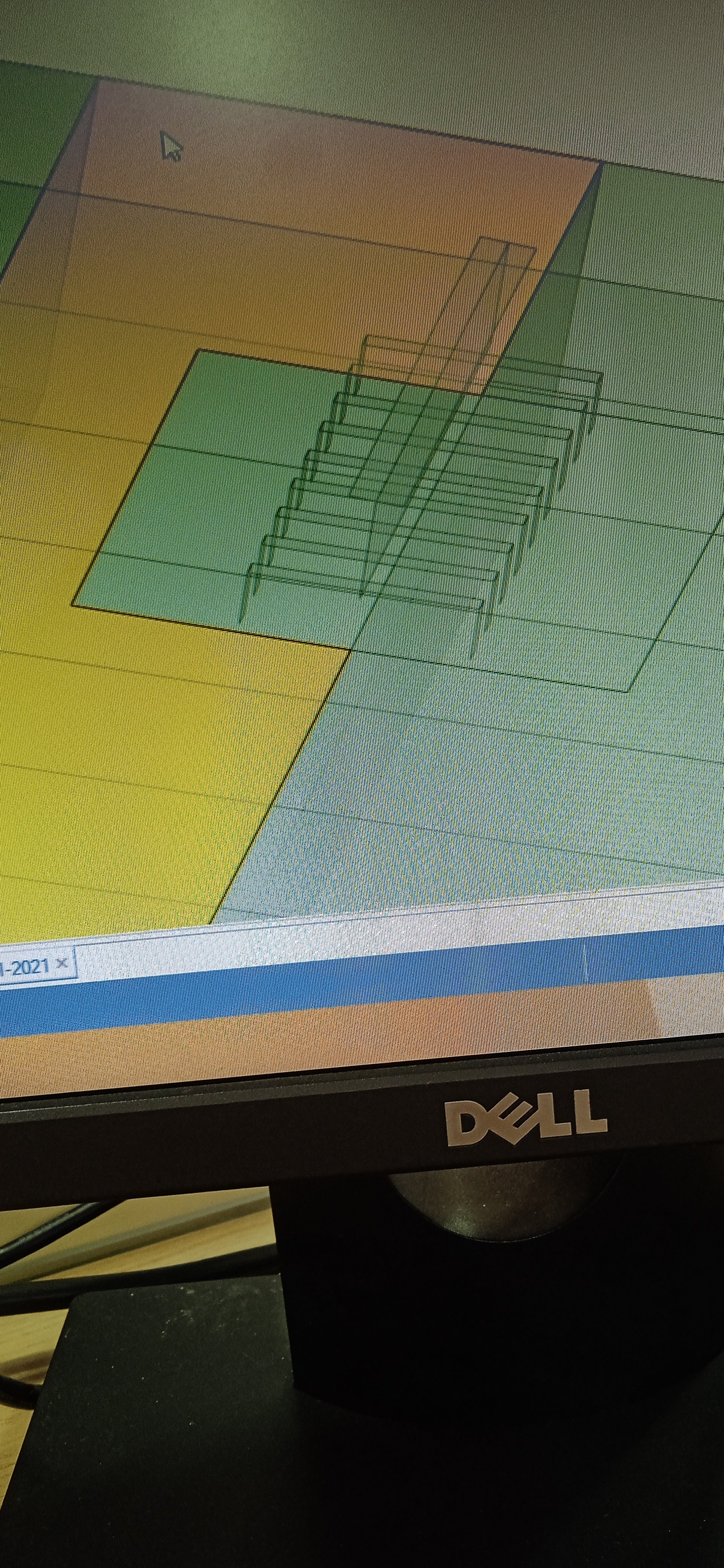
SubscriberThere one more similar case, where we made 25% model and instead of crane, this time over T girder, 900 horsepower volvo penta engine sit.
We wanted know that T profile will able to resist the inertial load, static as well as dynamic load.
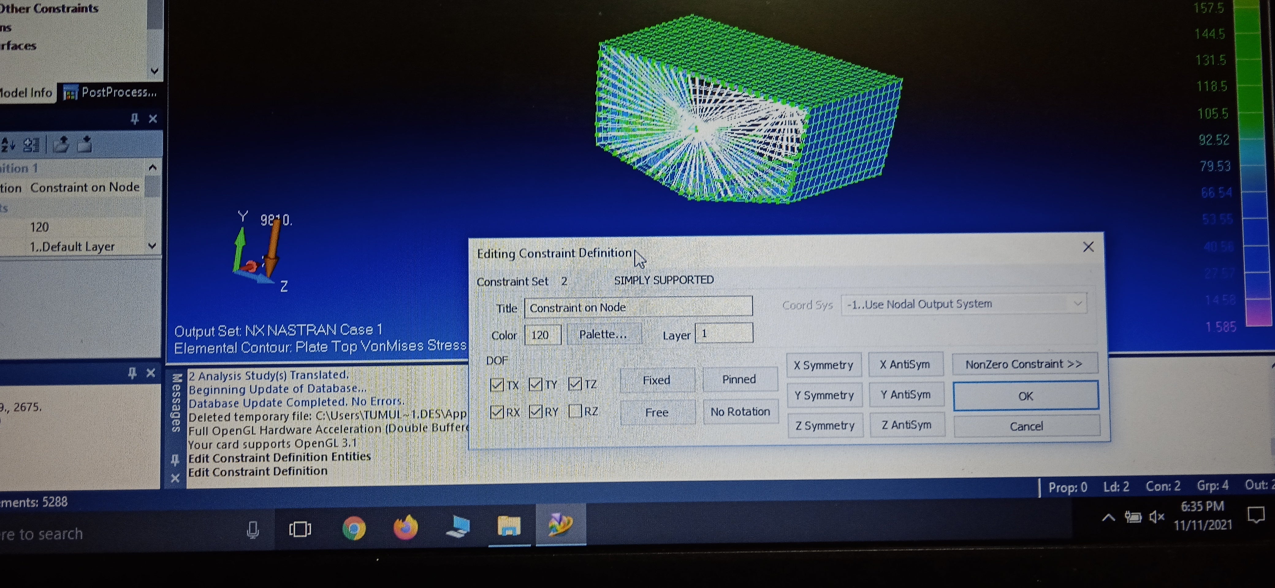
Here the boundary condition used you can see in photo
Do you have idea why Rz remained free?
On both ends, here they used rigid element constraints.
It's done in femap
November 13, 2021 at 1:04 pmpeteroznewman
SubscriberI also use Femap so am familiar with this dialog. One piece of information is missing, the Nodal Output System.
If the Nodal Output System is Global 0 as shown by the colored triad on the screen, I would say both RY and RZ can remain unchecked. The reason is there are two points spaced along X supporting this structure. That means only RX is required to prevent the hull spinning around the X axis. Leaving just RZ unchecked allows bending of the hull in the XY plane. Leaving RY unchecked allows bending of the hull in the XZ plane.
November 13, 2021 at 3:13 pmtumulpurwar
SubscriberThankyoui
First one important question of femap, if we check particular constraint in femap it means they are excluded, or included?
Second please if you could tell reason behind it, conceptual problem I guess I have
If RX constraint applied, than we can prevent rotation of ship supported between 2 points along X direction
But if we fix RZ it shows bending in XY plane? I don't understand
Why not ,if we apply RZ constraint, it can also prevent rotation of those two point about Z axis?
Please bear my broken understanding of dof, BC & elements.
I really want understand this.
Thank you peteroznewman
November 13, 2021 at 7:18 pmNovember 14, 2021 at 12:23 pmtumulpurwar
SubscriberHello peteroznewman
Thank you for this nice picture.
It means, even if Rz = 0(RZ is constraint, letting beam to not let rotate about X axis) right?
But still beam show deflection in XY plane.
I don't understand, what's relationship of rotation with beam deflection?
Can you guide, the problem is more going toward I guess my structural concept.
Please let me know.
Thankyou peter
November 14, 2021 at 1:10 pmpeteroznewman
SubscriberYes, ANSYS requires RX = 0 to solve the matrix. Without it, there is no solution.
One more picture I didn't draw would be a hull floating in water. There would be many small arrows pointing up to balance the single big arrow pointing down. There would be no bending of the beam, so there would be no difference between RZ=Free and RZ=0. There would just be a local stress around the point load at the center.
Finite Element Analysis is a numerical method to solve Boundary Value Problems. The Boundary Values are the constraints at the ends and the force in the middle. X,Y,Z,RX is one set of Boundary Values, X,Y,Z,RX,RY,RZ is a different set of Boundary Values. The Boundary Values are used while solving the Differential Equations and result in different solutions. Here is a lecture on the solution of the prismatic beam equations.
https://ocw.tudelft.nl/wp-content/uploads/sites/2/Bending-Deflection.pdf
November 14, 2021 at 2:32 pmtumulpurwar
SubscriberThank you very much Peter for bearing my broken knowledge and giving me guidance in clearing out my various doubts throughout.
One of the photo which I shown you earlier also, I am attaching again:
I got a comment from person who set that boundary condition in Femap. He commented:
Question I asked: So why in global analysis rotation about Z is free ?
His reply: If you are adding SWBM(Still water Bending Moment) then ur case( in photo) is global analysis then rotation about longitudinal axis in ur project(in photo) Z axis is needed to be free. Because SWBM(Still water Bending Moment) and wave bending moment is maximum in head sea condition and in that condition rotation about longitudinal axis is important.
Question again I asked: But in this photo, rotation about transverse axis is free, not longitudinal I guess.
He replied:Rotation in longitudinal axis means u have to free transverse axis.
What he is trying to say, I don't understand.
Please it's, my last question, I already appreciate your all support in last all comments.
And sure I will go through this pdf you attached.
Appreciate your support and help Peterƒæì

November 14, 2021 at 2:58 pmpeteroznewman
Subscriber Using the FEMAP image and my beam models above, the length of the hull or beam is along the X axis and Y axis is vertical, so Z axis is out of the page. He is saying that when a hull goes head first into a wave, the hull will bend along the length of the X axis in the XY plane as I have shown. Bending in this way requires each node along the length to be free in RZ. That is all he is saying. I would ask him why RY is not free.
November 14, 2021 at 3:50 pmtumulpurwar
SubscriberThankyou I understand, but when our bending is still in XY plane, and bending has nothing to do with rotation, than why we need care so much to free RZ?
Or else bending requires nodes to get rotate which are taking part in bending of, for example say beam. ( I am not sure)
I don't know how nodes degree of freedom act or behave when they face bending.
Sorry my stupid doubt
November 14, 2021 at 7:14 pmpeteroznewman
SubscriberIf all the nodes in a model made of shell elements (or beam elements) had RZ = 0, there would be no bending of the beam in the Y direction, there would only be shear deformation.
November 15, 2021 at 3:20 amtumulpurwar
SubscriberGot it finally , my all doubts covered up. Thanks a lot Peter.
Just one wish:
If I use this 25% hull as solid element and without bending and with bending how will be boundary conditions?
Normally what I know solid element doesn't support rotation(RX, RY, RZ), thus no resistance against Rotation.( example beam connected with solid element, here if we provide beam a load( like cantilever case) , thus other end of beam connected with solid element will not get resistance, thus no transfer of moment.
And if I use T girder only as solid element, rest as shell element, do I need set specific connection between solid element made T girder and rest of shell element of model?
Thanks
November 15, 2021 at 3:28 ampeteroznewman
SubscriberWhen a model is meshed with solid elements, each node has only translational DOF, but when a whole face of a model is put into a Remote Displacement, the pilot node for the BC has all six DOF. The Rigid element transfers forces to each node to keep the nodes on the plane, even through the plane can rotate as a whole if RZ is free on the pilot node, or kept vertical if RZ = 0 on the pilot node.
When a model is meshed with solid elements, it is important to avoid applying forces to a single node because that would create a singularity in the stress field. It is important to apply forces to an area.
November 15, 2021 at 2:14 pmtumulpurwar
SubscriberThankyou peter.
The Rigid element transfers forces to each node to keep the nodes on the plane, even through the plane can rotate as a whole if RZ is free on the pilot node, or kept vertical if RZ = 0 on the pilot node.
The plane you talking about is XY plane in above statement?
In shell case, if RZ free, it just gives bending in XY plane, but here, don't we get bending on XY plane if RZ free?
Kept vertical pilot node means if RZ =0? What it means?
One more question, I attached photo below, it's case our old 25Ôäà sliced hull hanged between 2 nodes.
In our old conversation,Earlier we were only applying local load of crane weight on T girder,along with hydrostatic load( pgh) while making both extreme nodes fixed or remote displacement.
But now we have value of bending moment of whole complete hull, and bending is coming almost near to middle of length of full hull.
So it means local crane load + hydrostatic load(pgh) + also want apply global bending moment of full complete length hull.
Can we apply the global bending moment while maintaining the case of simply supported beam?
As my hull is sliced and made only 25 % because of time limit, how to add this global hull bending moment?
Is bending moment we can apply in the middle of hull or just it will be applied only in either side of extreme ends of hull that is nodes in ansys?
Sorry as we are applying global bending moment,so we will exclude hydrostatic load, As bending moment itself is calculated taking all effects of static ( hydrostatic) and dynamic loads.
Thank you peter
November 15, 2021 at 5:17 pmpeteroznewman
SubscriberThe Rigid element transfers forces to each node to keep the nodes on the plane, even through the plane can rotate as a whole if RZ is free on the pilot node, or kept vertical if RZ = 0 on the pilot node. The plane I am talking about is the YZ plane that is the cut boundary at the 25% station of the hull. That plane can rotate about the Z axis if RZ is Free, or be kept vertical (parallel to Y axis) if RZ = 0.
If you know the bending moment at the 25% station of the hull, you can apply that as a moment to the remote point as a Moment load about Z. Use the same remote point in the Remote Displacement but leave RZ Free.
November 15, 2021 at 6:21 pmtumulpurwar
SubscriberSo I guess I need to
Use the same remote point in the Remote Displacement but leave RZ Free on one extreme end and let other extreme end remote displacement just with RZ free, no remote point?
Right?
And rest other dof in remote displacement leaving RZ will be 0?
Right?
don't know how to thankyou, it could be very little of it.. May be it can be your job or not, but you are one of the most helpful and sound person.
Really thanks a lot for immense patience Peter.
You made me quite confident from quite weak.
Merci.
November 15, 2021 at 7:52 pmpeteroznewman
Subscriber"let other extreme end remote displacement just with RZ free, no remote point?"
A remote displacement uses a Remote Point whether it is made explicit (Promote to Remote Point) or left internal.
Leave RZ Free at each end to allow a bending moment to be applied.
November 16, 2021 at 2:08 amtumulpurwar
SubscriberThank you Peter.
Two more questions:
1) do you think still I need apply hydrostatic load( still water pressure) ( Pgh)( on down side of hull, upto my draft, because now I am applying at sliced frame this bending moment and on the top deck, there will be crane weight load on T girder which I will apply?
I think no. I am not sure
2) if we are using say complete hull by length, no more sliced hull, than do we still use remote displacement on both extreme ends? As now our hull is full lengthwise, so no more remote points needed. So what should we apply at the end points? (And yes we still need apply bending moment at one of the extreme point)?
Thanks
November 16, 2021 at 2:08 pmpeteroznewman
SubscriberA hydrostatic load is useful to counterbalance the weight of the hull, which means a Gravity load must also be present. If you have the correct draft line, the net upward component of the hydrostatic load will exactly match the weight of all the parts in the model plus the crane weight load represented as a downward force.
Even when you have a perfectly balanced set of loads, Static Structural needs a stiffness matrix that is not singular. That is done by constraining all six DOF of rigid body motion. You are doing that with the two remote displacements. In this case, the reaction force will be close to zero.
I don't know how global bending moments for ship hulls are computed and what conditions they apply to. Are they intended to replace using the loads I described in my first paragraph?
November 16, 2021 at 3:06 pmtumulpurwar
SubscriberHello Peter
For global bending moment, we take cantilever beam case, where one end is rigidly fixed, and other end is set to be free in all dof, meanwhile on this free side (or node) we apply global bending moment numerical value.
I think as even my sliced hull case, I have global bending moment value, which is occuring in middle of vessel almost, in region where also my crane load in near region acting.
And I don't have local bending moment at sliced frames (extreme nodes)
Now if you understand, I have two loads:
1) crane load acting near to region where bending moment of whole hull is maximum
2) offcourse & this bending moment value( global bending) or a bending maximum value , because we are interested in knowing when our ship can face maximum bending load.
And as ship is symmetric, most of time maximum bending we see in the middle region of ship.
In my case it's not 100% middle bit offset from middle.
But my cute little sliced geometry of hull, is a, part where maximum bending of complete hull will show maximum stresses.
As well as, luckily the crane load also acting in that area.
So my little sliced structure contain both important region, as this region will face maximum bending and as well as will face crane load on top deck.
Now because I can't make full hull structure it's time consuming, I am left with option of sliced hull, my idea is I will play with density of sliced structure, I will replace with whole hull structure density and apply those remote displacement conditions which you told?
What you think it's correct idea, to get correct stress without making full model??
Need your suggestions
If we consider a heavy solid rod 1 meter long for example, and due to some reason, I can only make 30% of solid rod.
If we apply bending to rod on one end, and just put density of full length rod, it will still give correct bending stresses I guess at any section of rod?
And as rod shape is uniform it will be more easy.. Normally ship are symmetric too and uniform on both sides.
One more question when we are applying here maximum bending moment of full length ship, which is coming maximum probably near centre... I guess do we still need apply hydrostatic load? (Pgh)?
I guess this global maximum bending value probably would have been calculated taking the upward reaction effect of hydrostatic load? I guess?
So no need again take hydrostatic load? I think?
Thanks
November 16, 2021 at 3:28 pmtumulpurwar
SubscriberHello Peter
Whatever we have discussed earlier specially about RZ free stuffs in boundary condition, I think these are needed when we have simply supported case, I guess... , it was simply supported, until global bending moment not came in picture,
And if we applying bending moment on one end and , we need free all degrees here and on other side fix all dof, meanwhile also let local crane load to let remained apply on top deck
What you think?
If you take simple civil engineering case, cantilever applied with bending moment on one side, so most common boundary condition I ever came across is
One node all dof fixed and other node where we apply this beam bending moment, let that node remain free in all dof
November 16, 2021 at 3:38 pmtumulpurwar
SubscriberThe photos I am attaching done in femap. You can se all condition also
November 16, 2021 at 4:07 pmtumulpurwar
SubscriberI think it's possible Peter, that we can have cantilever beam with moment applied on one end, leaving all dof free in this node and other fixed.
I don't know your RZ leaving free and other fixed in cantilever beam will fail I guess?
Ok I guess with all rotation free, RX, RY, RZ, we will see bending on all 3 plane combination? XY, YZ and ZX? Right? But you told in earlier comment, RX =0, needed to solve matrix in ansys.. It means no YZ plane bending???
But what with translation, as you not told to make all translation free also, but in the photos you can see all translation free too, in cantilever case.
And also this cantilever facing point load at near middle of ship from crane ?
And of course we are doing it in ansys
Note: very stupid question, whenever you say, RX = 0 or X =0, it means fixed?? Right.. Not free offcourse.
I look for your solution and views
November 17, 2021 at 2:09 amtumulpurwar
SubscriberHello Peter, I don't know how to delete last 3 comments, you can avoid reading them as I understood now.
Just one question I have still.
For applying moment, I will take it remote point & scope it in rote displacement and also in remote displacement I will use RZ free to get bending of ship in XY plane, but in remote displacement other dof like RY, RX and even translation they all will get zero?, it means fixed? Right?
Why people use even all rotation and translation free when apply moment to that particular node( like cantilever case) ?
And whether this remote displacement( rigid) will give correct stresses, if I apply scoped moment about one extreme node?
I saw your one post, where you were talking about remote displacement, there you told to apply tip force to get correct stresses, you told applying same displacement at remote displacement won't give correct stress, probably will show more stress.
Viewing 38 reply threads- The topic ‘Rigid body element & Master Slave joints’ is closed to new replies.
Innovation SpaceTrending discussionsTop Contributors-
5094
-
1830
-
1387
-
1248
-
1021
Top Rated Tags© 2026 Copyright ANSYS, Inc. All rights reserved.
Ansys does not support the usage of unauthorized Ansys software. Please visit www.ansys.com to obtain an official distribution.
-

