
-
-
December 23, 2021 at 7:41 am
Alexander19
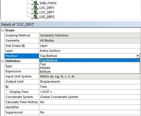
SubscriberI am simulating deformation of a Shell body (SHELL181). I want to know location of the top and bottom surfaces of this Shell body after deformation so I inserted user defined results as shown in the Figure below. However, there is no difference when I chose Top , Bottom ( at "Position" option).
December 23, 2021 at 4:34 pmRameez_ul_Haq
Subscriber,if you already are using a SHELL181 element, then just directly looking at the results of deformation means that you are actually seeing the deformations (that are supposed to happen) on the top face, as well as on the bottom face. I don't think any external user defined results are necessary.
December 24, 2021 at 3:09 amSubscriberThank you for your reply. Because I want to know surfaces after deformation. Actually, there is no change of thickness in the postprocessing figures.
December 24, 2021 at 6:51 amSubscriberthe thickness should be changing ofcourse. Try exaggerating the results scale factor. Then you might be seeing the change in thickness. We use SHELL181 (and SHELL281) to actually observe the change in thickness as well when subjected to loading conditions.
What do you mean you want to know surfaces? If you are only interested in the top and bottom faces deformations (infact, deformations along each of the axes like X, Y and Z), then just observe it. You will be seeing different results on both of these faces. Use Probe to check the deformations at any location within the body.
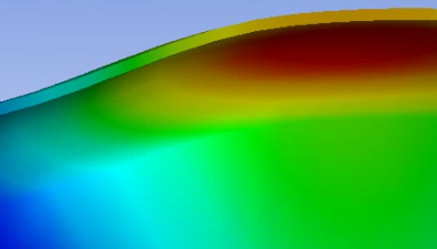
December 24, 2021 at 8:09 amSubscriberI already tried to observe but it seems only contour of change of thickness can be plotted as shown in the Figure below. (I use Ansys 19.2).

December 24, 2021 at 10:52 amSubscriber,SHELLTHICK is used to determine the thickness of the shell. Its not about deformations. What you are trying to do (as far as I have understood, you actually want to see the deformations of the top and bottom faces separately), can directly be seen from the deformations plots when you right click the solution. No user defined results are necessary at all.
December 24, 2021 at 11:14 amSubscriberSorry for the unclear question. Now, I want to see the deformed shape in which different shell thicknesses were shown. Is there any option to do that? Because as you mentioned before, it automatically shows the change of shell thickness. However when I plot the result of deformation (below picture), the shape is deformed but the thickness is still uniform ( It must be different as shown in the previous picture with contour of thickness). In my opinion, because it is shell body, actually, there is only one grid-layer, so Ansys cannot plot the change of thickness as for solid body.
December 25, 2021 at 1:51 pmSubscriber,I am not sure if the thickness changes during the solution or not for a SHELL181 element. Maybe an Ansys employee can help you here.
December 29, 2021 at 12:36 pmAshish Khemka
Forum Moderator
It may be a workbench limitation. You can try seeing the image in Workbench using the following APDL comand:
SET, LAST!Select last result set
/GRAPHICS POWER!Activate power graphics option
/VIEW,1,1 !Defines the View of the Display
/ESHAPE, 1.0!Activate the Thickness shell option
/SHOW png ! Save the image in png file
PLNSOL U SUM ! Print Nodal Solution
Regards Ashish Khemka
Viewing 8 reply threads- The topic ‘Results at Top and Bottom surface of a Shell body’ is closed to new replies.
Innovation Space Trending discussions
 Top Contributors
-
peteroznewman
 5799
5799 -
scabo
 1906
1906 -
Dennis Chen
 1419
1419 -
javat33489
 1305
1305 -
Shyam Prasad V Atri
1021
Top Rated Tags
© 2026 Copyright ANSYS, Inc. All rights reserved.
Ansys does not support the usage of unauthorized Ansys software. Please visit www.ansys.com to obtain an official distribution.
-


The Ansys Learning Forum is a public forum. You are prohibited from providing (i) information that is confidential to You, your employer, or any third party, (ii) Personal Data or individually identifiable health information, (iii) any information that is U.S. Government Classified, Controlled Unclassified Information, International Traffic in Arms Regulators (ITAR) or Export Administration Regulators (EAR) controlled or otherwise have been determined by the United States Government or by a foreign government to require protection against unauthorized disclosure for reasons of national security, or (iv) topics or information restricted by the People's Republic of China data protection and privacy laws.
