
TAGGED: force-reaction, nodal-force
-
-
September 10, 2021 at 1:56 pm
Rameez_ul_Haq
SubscriberPlease observe the pictures below.
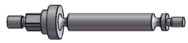
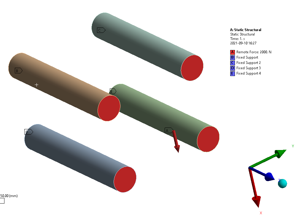
MODEL [remote force is in the center but a few mm forward in the z direction]:
September 13, 2021 at 7:15 amSubscriber,can you please comment about this? :)
September 13, 2021 at 8:55 pmpeteroznewman
SubscriberYou didn't mention if the Remote Force had the behavior set to Deformable or Rigid.
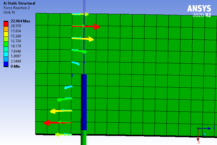
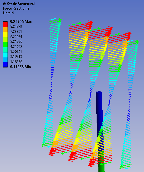
First question, why do the force vectors go in two directions? Because the beams are shearing and bending and the top is in tension while the bottom of the beam is in compression. You seem to call the four rods a "beam". If you had a long solid beam with a tip force, the material above the neutral axis would be only in tension. But you have a short beam made up of four rods, so they behave differently than what you were expecting.
Second question. Nodal forces depend on the mesh. If you have a cross-sectional area and fill that with 8 nodes, the forces will be very high compared with the same area filled with 80 nodes. You don't use the maximum nodal force to size the beam. The resultant force tells you the shear force and axial force. Knowing these values you can select a cross-sectional area that keeps the stress below yield by a large Factor of Safety.
Third question. The applied force has no Y component so there is no Y component in the Reaction Force. There is nothing to consider when sizing the beam in the Y direction.
September 14, 2021 at 8:14 amSubscriberthank you sir for replying.
The behavior is set Deformable. But why does this matter? A brief elaboration would be beneficial.
To be honest, I couldn't actually understand your answer about the first question I asked. Lets just call each of the 4 solid cylinders in my model as a rod. Now, shouldn't the rod that I have picked in my second picture only be in tension? I mean you are right that I was trying to make ANSYS believe that these 4 rods actually belongs to a single structure. But I think since I didn't do this, thats why I am seeing both tension and compression in the rod of concern. This makes me believe that each rod has an individual neutral axis and the overall neutral axis of the whole model is not even considered by ANSYS. Am I right? If yes, then what can be done to make the ANSYS believe that these 4 rods belong to a single structure, and a general overall neutral axis should be taken into account.
Plus, if ANSYS considers individual neutral axis for each of the rod, then why do I see a net force in the Z axis for the concerned rod when there isn't any external force applied in the Z axis? I mean shouldn't there be only a net moment in the second and third picture, but no net reaction force in the Z axis? Isn't it?
Your answer to my second question is also a little bit baffling. I mean you thaught me that the mesh size doesn't matter to calculate the total amount of force passing through a rod or a cross section of a body. It all depends upon the general equilibrium of the body that how much force is passing through a cross section of a body. We can use Rigid Dynamics for that directly as well, where meshing doesn't even play a role. Mesh is only required to calculate the displacements and stresses in the structure within a certain accuracy. But now you are saying that the the net nodal forces in a cross section depend upon how many nodes I have in a cross section. Confused ! This discussion also hits my brain with another question. Like if only resultant shear and axial forces should be used, then why do we have a stress calculation equation which depends on bending moment only. Since in a bending due to transverse loading case, there won't be any net resultant axial force in a cross section but a bending moment will exist. So the question actually becomes when should the bending moment be used, and when should the net resultant axial force be used? (For a cross section of a rod or any other body).
Regarding your last paragraph, I would like to ask something. I mean at the fixed support locations, we know that the ANSYS is applying a Y axis reaction force there to keep those faces not displace in the Y direction (Poisson's ratio effect). However, since there isn't any external Y force, the net resultant Y force at these fixed faces should be zero. We know this. But these forces are being applied, and causing extra stresses near these fixed supports, so this means that it should play a role in sizing of the beams. Maybe by using a torque about Z axis, or maybe not. Or maybe something esle. I don't know. Can you please say something about this?
September 15, 2021 at 7:33 amSubscriber,can you kindly provide your views on this one please :)
September 15, 2021 at 12:02 pmSubscriberDeformable vs Rigid Remote Force can make a large difference because Deformable adds no stiffness to the structure while Rigid adds stiffness to the structure! In this example, deformable behavior allows the end faces of the rods to individually rotate while bending. Rigid behavior enforces the end faces of the rods to rotate as a rigidly connected group. I suggest you run the model both ways and look for the difference.
First question. A neutral axis is a concept used in the formulation of beam elements. A solid mesh does not have a neutral axis included in the formulation. Try to build the four rods from beam elements and see what you get. The forces in the solid rod elements make sense to me. Maybe when you flip the behavior of the remote force, you will get a different result that makes sense to you.
Second question. It is correct that the total force through a cross-section is independent of the mesh. I never said "the net nodal forces in a cross section depend upon how many nodes I have in a cross section". You asked "how can I find the maximum force (among all the nodes) at a specific cross section". I took that to mean you were asking about individual nodal forces and replied that you don't care about nodal forces because they depend on the mesh.
Bending moments apply to beam elements. There is no such thing for solid elements, which only know about forces. You can infer that the net resultant of the forces applied to the face of a solid mesh imply that a moment is being applied to that face.
Last paragraph. You design the area around a fixed support to avoid the stress created by Poisson's ratio by simply flaring out the material to a larger cross-sectional area. Below is an image of a rod flexure that illustrates this point.
 September 15, 2021 at 2:07 pmSubscriber,I actually know the difference between Deformable and Rigid and what I can expect from the results. (You thaught me that as well before ). I was actually confused that why and how could it affect my sizing process. I mean since I am not applying any external loads in any other direction than X axis, so the extra forces can form on those faces of the rods (where the remote force is scoped) if the behavior is Rigid, but they have to cancel out each other. I don't know if the net force of all the 4 faces will be zero in all other directions (except X), or each face needs to have a zero force in all other directions (except X). Anyhow, it is kind of like a fixed support. In your previous comment, you said that "The applied force has no Y component so there is no Y component in the Reaction Force. There is nothing to consider when sizing the beam in the Y direction." So it kind of appealed to me as if rigid and deformable won't matter at all if we want to size the rods. It would affect the stresses, yes, but for sizing, I am not sure.
Moreover, in your recent comment, you said that "You design the area around a fixed support to avoid the stress created by Poisson's ratio by simply flaring out the material to a larger cross-sectional area". Well, yes I agree with what you said. But spreading out the material to a larger cross sectional area will require some calculations, isn't it? I mean how would I know how much bigger area should to used near the cross section and when should this enlargement of the cross section area begin (I mean at which length). My understanding is that this requires calculations and for that, we need to know how much extra forces ANSYS is putting in because of the poisson's ratio effect. Am I right here, what do you think Sir?
I couldn't grasp why are you saying that "The forces in the solid rod elements make sense to me." I mean I am not applying any load in Z axis to any of the rod, but I am getting a resultant load in a rod along the Z axis. If this is the case, then why am I seeing a positive force vector and negative force vector along Z axis in the second picture I shared. The vectors in the + Z axis look similar in length to the vectors in the - Z axis. This means they should cancel out somehow. But I am seeing a net Z axis force. Similar to what I asked about the fixed support (also shown in the second picture); a net resultant force exists along the Z axis but don't you think a resultant moment should exist there only (I am not talking about the moment inherently coming from the node themselves, but the moment which should exist because of equal but opposite forces on that face along Z axis)?
September 15, 2021 at 11:01 pmSubscriberI can't answer all the questions in one go. I will answer the question in the last paragraph first and maybe post another reply to respond to the other paragraphs another day.
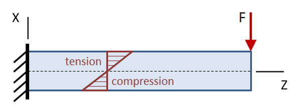
Below is a textbook image of the forces in a cantilever beam. The applied force is in the X direction, yet all the internal forces are in the Z direction.
 Here is the Ansys Force Reaction plot. That is why I say the forces in the solid rod make sense to me.
 September 16, 2021 at 12:23 amSubscriber"How would I know how much bigger area should be used near the cross section and when should this enlargement of the cross section area begin (I mean at which length)."
You would start with an initial design concept, such as the rod flexure example I provided above, build a FEM of the initial design, look at the results and come up a list of changes that become the first design iteration. Update the FEM, look at the results, come up with more changes that become the second design iteration. Continue iterating until the design meets all the requirements, or is optimized for some metric such as minimum mass. The iterations can be manual or you can use some of the tools Ansys provides to automate the iteration.
September 16, 2021 at 7:32 amSubscriberthank you for replying and answering the queries. I always appreciate your willingness to help engineers like me :)
Regarding your first of the last two replies, can you please also share the net 'results' for the forces and moment on that surface (just before the fixed support)? My expectation: NO NET FORCE ALONG Z AXIS but A NET MOMENT ABOUT Y AXIS EXISTS.
Your second of the last two replies was helpful, thank you. Understood that :)
September 16, 2021 at 12:15 pmSubscriberAs expected, there is no net force along the Z axis. If you slice this beam in half horizontally so there is an upper and lower member, obviously, the upper member (or rod) will have a net force in Z and the lower member will have the opposite net force in Z.
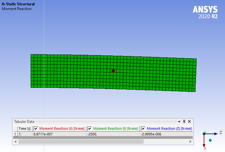
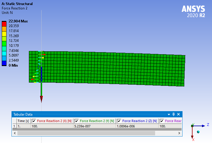 There is a Net Moment about Y.
 The image below is the same model but meshed with 100 elements through the X direction thickness. Note that the maximum nodal force is much smaller than the coarse mesh above, 9.2 N instead of 22.9 N, which illustrates what I said above about how maximum nodal force (not net for the section, but individual nodes) depends on the mesh.
 September 16, 2021 at 12:43 pmSubscriberthank you for sharing your case study here :)
This is exactly what I was saying about the model pictures I shared. If you look at the last picture I shared in the question, there exists a net force along Z axis on the fixed support, and also there exists a net force along Z axis at a cross section but before the fixed support (as shown in second picture). This is confusing for me that where is this net force along Z axis arising from. This is what I have been asking in this thread actually. A net moment if exists about Y axis, makes sense. But a net force along Z axis, completely puzzled. How and why?
September 16, 2021 at 11:53 pmSubscriberYou didn't seem to understand my point about slicing the single beam horizontally, so I have done that explicitly to show you the results. Below is the applied Force at the tip.
 There are now two fixed supports, one for the top arm and one for the bottom arm at the left. Each one has a Reaction Force.
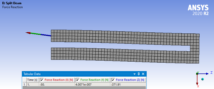
 So the total force in X is exactly -100 N, to balance the 100 N at the tip, while the Z force reactions are equal and opposite 371.91 N on the bottom and top end faces to balance out the moment. Since they cancel each other out, at a surface that cuts through both legs, the Force has a net zero for the Z direction.
 I hope this helps you understand.
September 17, 2021 at 8:47 amSubscriberthank you for your clarification. Now just assume I want to remove half of the part from the right side, and keep the left half (including the supports). So should I be using Rigid remote force or Deformable on the cut faces of the (now after cut) two separate beams?
September 18, 2021 at 8:19 amSubscriber,your suggestion on this one would be helpful :)
September 18, 2021 at 5:00 pmSubscriberThe structure I created is a parallel beam flexure, but with really thick beams. A proper version of that would have thinner top and bottom beams, but keep the small block at the end. It would be incorrect to cut this structure in half to remove the right side. The full length of the beam is required to correctly represent the stiffness of the flexure. If you wanted to minimize node count, you would replace the solid body with two surfaces and mesh with shell elements. These could be bonded or node merged to a small block meshed with solid elements where the surface overlaps the end of the small block.
If instead of a small block at the end, there was a large stiff block of material, it would be appropriate to cut off that large stiff block at the plane where the current small block ends and use a Remote Force using a Rigid behavior.
September 18, 2021 at 5:46 pmSubscriber,"It would be incorrect to cut this structure in half to remove the right side. The full length of the beam is required to correctly represent the stiffness of the flexure.". Why so? I mean if I have a solid rod with length of 100 mm and I apply a transverse load at right end with left end fixed, then the displacement and stress results at the half of the beam i.e. 50 mm would be same if I cut theis solid beam in half and put a remote force at the cut cross section (at the same location as in first case), isn't it?
Plus, does the remote force also change location with the displacement of the cross section during solution in a non-linear solution? We know that the direction will still be the same but what about change in location of the remote force during solution as the general force does?
September 18, 2021 at 6:59 pmSubscriberIf you keep the location of the rigid Remote Force at the full length of the beam and scope it to a cut face half way along the length, that will reproduce the deformation and stress of the first half. However the deformation of the remote point would be incorrect compared with the full length beam because the second half, which was flexible and contributing to the tip deformation, has been replaced with a rigid element.
So if you don't care about tip displacement and are only focused on stress in the first half, you can use a Remote Force. But if you need both the stress in the first half and the tip deformation to be correct, then you can't use a remote force. Stiffness is Tip Force/Tip Deformation so that requires the full model.
Plus... remote points update their location when large deflection is turned on.
September 18, 2021 at 8:44 pmSubscriberIf you cut the length in half and applied the remote force from the original length of the beam, you would indeed have the same stress and displacement of the first half, but the deformation of the remote point would not match the deformation of the tip of the full model. The reason is the flexible second half was replaced with a rigid element. Stiffness = Force/Deformation which is why the stiffness would be wrong for a remote force versus the full model.
Plus...remote points update their location when large deflection is turned on in a nonlinear solution.
September 18, 2021 at 8:54 pmSubscriberthis might a little in depth but I was just wondering that since the location of the forces change in a non-linear solution, this means that the displacements and stresses value will change as the solution proceed, by taking into account the change in location of the force as well. For example, when force was applied at a 100 mm tip of a fixed end beam, then at final time, the force might have moved 1 mm along the length direction of the beam. This means that the moment at the fixed support has decreased and hence the stresses at the mid of the beam would not be the same if the force wouldn't had moved at all (as like in a linear analysis). I was just wondering that if the right half is removed and replaced with a Rigid element, then this force location change along the direction of the beam would be lesser than what it would be if whole beam was considered in the model. This means we cannot claim that the stresses on the left half would be the same as when the whole beam is considered in the model.
I hope you understood my query here.
And why can't I use Deformable Remote Force for this situation (i.e. when only left half of beam is the area of study).
September 19, 2021 at 4:17 amSubscriberSure, in nonlinear, there are all sorts of second order effects, so nothing will be the "same", they will just be similar.
Beam theory assumes plane sections remain plane. A rigid remote force maintains this assumption, a deformable remote force does not.
Viewing 20 reply threads- The topic ‘Resultant force reactions for a structure under bending.’ is closed to new replies.
Innovation Space Trending discussions
 Top Contributors
-
peteroznewman
 5039
5039 -
scabo
 1729
1729 -
Dennis Chen
 1387
1387 -
javat33489
 1248
1248 -
Shyam Prasad V Atri
1021
Top Rated Tags
© 2026 Copyright ANSYS, Inc. All rights reserved.
Ansys does not support the usage of unauthorized Ansys software. Please visit www.ansys.com to obtain an official distribution.
-


The Ansys Learning Forum is a public forum. You are prohibited from providing (i) information that is confidential to You, your employer, or any third party, (ii) Personal Data or individually identifiable health information, (iii) any information that is U.S. Government Classified, Controlled Unclassified Information, International Traffic in Arms Regulators (ITAR) or Export Administration Regulators (EAR) controlled or otherwise have been determined by the United States Government or by a foreign government to require protection against unauthorized disclosure for reasons of national security, or (iv) topics or information restricted by the People's Republic of China data protection and privacy laws.
