TAGGED: fatigue-analysis, fatigue-life
-
-
June 4, 2024 at 6:03 am
-
June 4, 2024 at 9:37 am
Kaushal Vadnere
Ansys EmployeeHi Sneha,
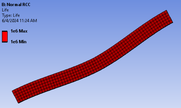
What is the magnitude of the load being applied, is it very low compared to the dimensions? If the stresses in structure are significantly low, it is normal to have 1e6 cycles minimum and you may not see any reduction in fatigue life at any point of the structure. 1e6 cycles is considered as infinite life for majority of the materials and hence it is considered as standard maximum value. Your model shows 1e6 cycles as minimum, standard interpretation of this is that your structure has infinite life and it will not fail due fatigue. If you see minimum value lower than 1e6 cycles, that means the structure does not have infinite life and may fail after given minimum cycles of fatigue loading.
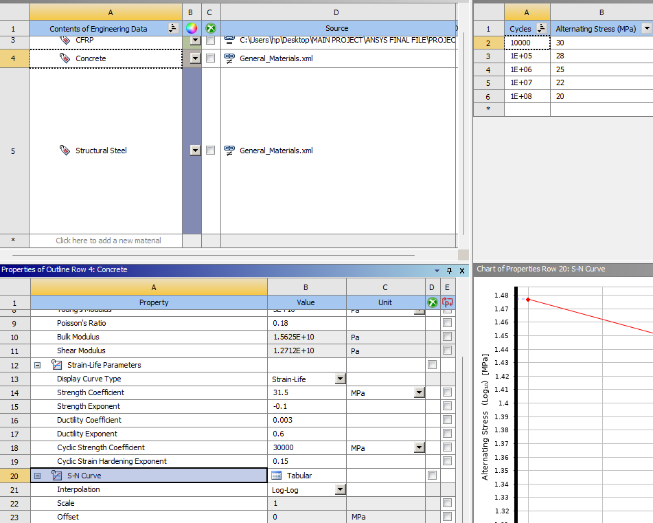
Also, the concrete material available in engineering data does not have a S-N or E-N curve defined which is needed for fatigue calculations. Have you added your own S-N or E-N curve in the material properties?
If not, can you check if the concrete is assigned to the geometry and not the the default structural steel.-
June 4, 2024 at 3:13 pm
Sneha E S
SubscriberThe magnitude of the load applied is 100 kN. The dimension of the beam is 3200x250x150 mm. I have added SN curve and strain life parameters to the material concrete for the purpose of fatigue analysis. The value was obtained from different journals. Also, if this minimum value indicates that the model is safe, then why is there different value at different regions for safety factor, doesn't that indicate the risk of failure at different regions. Or could anyone explain what does actually fatigue life, safety factor, damage and biaxiallity indication (all are parameters coming under the fatigue tool) means?
-
-
June 5, 2024 at 8:18 am
Kaushal Vadnere
Ansys EmployeeThanks for the details,
Are you applying 100kN as UDL?
For safety factor, what's the minimum value, can you put a screenshot for the safety factor contour as well?
Also, can you share details of fatigue tool (possibly a screenshot) to see what loading and options you've selected?
For your other question, you can find the definitions for fatigue life, safety factor, etc in the Ansys Help > Mechanical Users Guide here: 18.11.5. Fatigue Results (ansys.com)
Also, you can refer to this free TIDBIT on fatigue analysis, you will find a collection of knowledge materials that will provide you with some tips and tricks for performing a fatigue analysis in Ansys Mechanical: Performing a Fatigue Analysis using Ansys Mechanical | Ansys Innovation Courses -
June 5, 2024 at 10:54 am
Sneha E S
SubscriberI have applied load as point load at center of the beam. The boundary conditions are fixed and simply supported also three different materials are to be studied. For different cases I have obtained fatigue life with minimum and maximum value 0,10, 1+e8 etc. The plot for damage also shows the same values for those cases whereas safety factor has a contour plot with different values at different regions( adding an image, unable to add many pictures). I have to analyse the models with above conditions itself, cannot change any of those as my work is to study the fatigue behaviour in each case. So I just need an explanation for such results which I can use in my work. Also I am unable to access first link.

-
June 5, 2024 at 11:52 am
Kaushal Vadnere
Ansys EmployeeSure, you can find the help button in mechanical in the upper right corner (icon is question mark on blue background) and then click mechanical help in the dropdown. This will open help documentation in the browser. Inside the help document, Navigate to Using Results > Fatigue Results > Fatigue results. Here you will find the explanation to these result objects.
Have you defined analysis type in Fatigue tool as 'Strain Life'?
-
- The topic ‘Result shows same value for max and min’ is closed to new replies.


-
5044
-
1754
-
1387
-
1248
-
1021

© 2026 Copyright ANSYS, Inc. All rights reserved.


