
-
-
December 20, 2023 at 9:27 am
murali
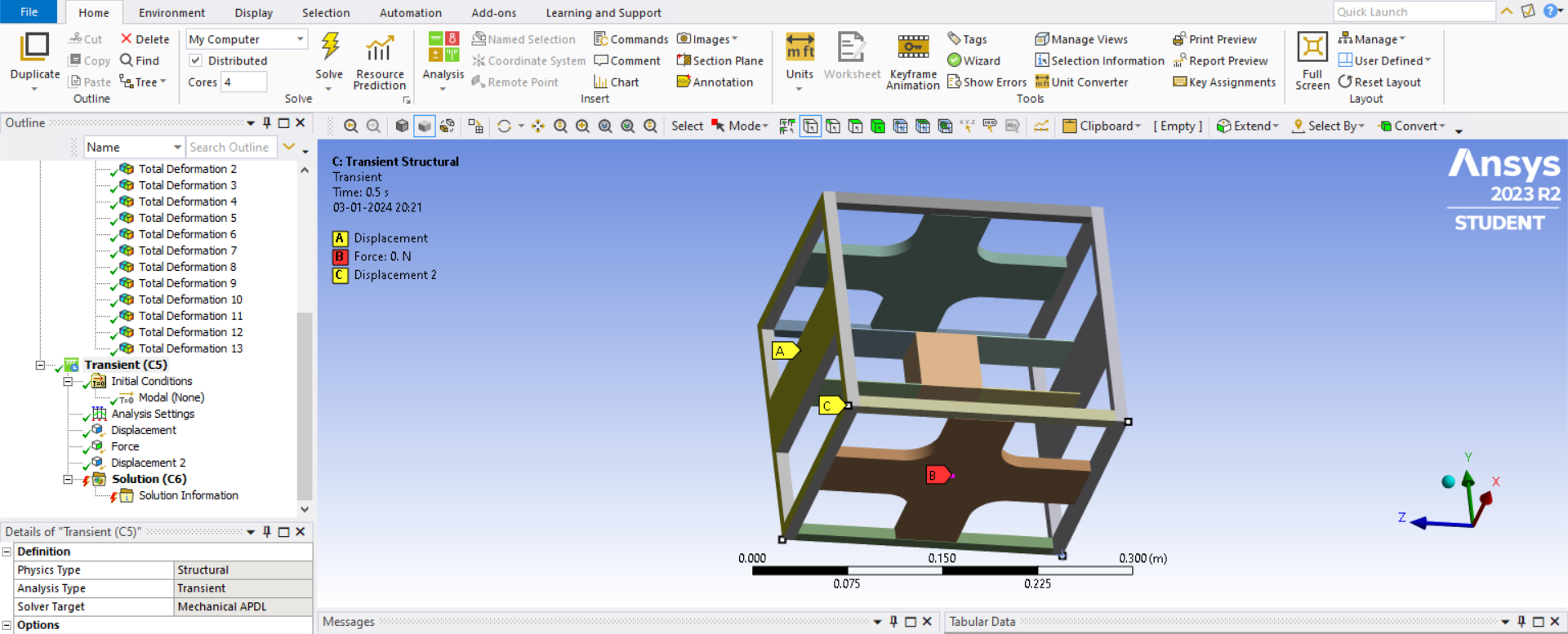
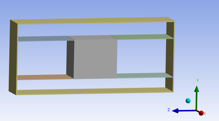
SubscriberI have an experimental rig with beam-mass system attached to a frame. The ends of the beam are fixed to the frame. I have modelled the system in workbench as shown. I need to simulate situation where a force is applied on the bottom of the frame in Y direction with an impact hammer. I need to find the response of the beam-mass system to this excitation. The frame is free to move in the Y direction. I tried to model this system using an impulse force in transient analysis.
Analysis settings:
3 step analysis with time step 1e-3 (natural frequency is around 25Hz)
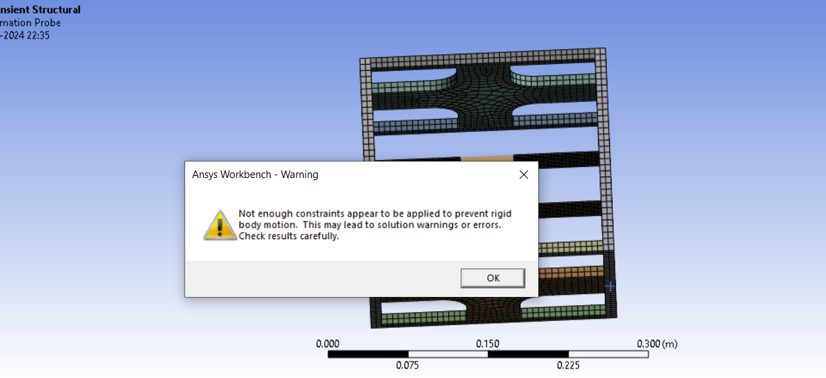
To be more clear, the frame is free to move in Y direction, the applied force on the frame creates a motion in the y direction. This motion should result in the vibration of the beam and mass attached to the frame. Which boundary condition should i give in this case for the frame? I tried restricting the motion in x and z directions, but the analysis fails with the error of insufficient bc and rigid body motion.
I just tried fixing the left and right sides of the frame to see if there is any response, but there is no motion of the beam and mass(displacement probe attached below).
-
December 21, 2023 at 4:24 pm
dlooman
Ansys EmployeeIn a Transient Structural System with time-integration turned on (default) it isn't necessary to have a fully constrained model. However, your impulse load is going to impart an initial velocity to the model which may make postprocessing difficult due to the large displacements. You could specify the pulse with a full sine wave so that the rigid body velocity was less.
-
December 22, 2023 at 3:30 pm
peteroznewman
SubscriberMurali,
Are you interested in designing for shock environments? A good reference is Vibration Analysis for Electronic Equipment by Dave S. Steinberg. Chapter 11 is Designing Electronics for Shock Environments. It describes various types of shock pulses used to test assemblies.
One type of velocity shock makes use of a heavy hammer that slams into a fixture that supports a test specimen. The hammer imparts a sudden velocity to the fixture and the test specimen. One test rig uses a 400-lb hammer for shock testing electronic assemblies that weigh less than 250 lb.
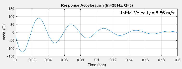
If you are designing support for the mass to survive a particular acceleration level when the frame is dropped from a height H, there is a formula to calculate the velocity change V. The velocity change depends on the coefficient of rebound C, which could be between 1.0 and 2.0 where a value of 1.0 represents no rebound while a value of 2.0 is perfectly elastic rebound. The formula is V = C*sqrt(2*g*H) where g is the acceleration of gravity. For example, if the rigid frame is dropped from a height of 1 m onto a perfectly elastic spring, the velocity change is 8.86 m/s.
Pulse shocks can be defined using various profiles such as half sine or symmetrical triangular which is what you used. However, these are generally specified using a peak acceleration in the units of G and a duration in seconds. The advantage of a shock specification in terms of acceleration is that it can be applied to a wide range of test specimen masses.
You show a force of 150 N, but what is the mass supported by the frame?
The natural frequency is 25 Hz, so if I knew the mass, I could calculate the spring rate from an equation. For example, a mass of 4 kg would be supported on a spring with a rate of 99 N/mm.
If the mass-spring system has a natural frequency of 25 Hz, you would want a shock pulse that has a lot of content at that frequency. The period of 25 Hz is 0.04 s. Half of that is 0.02 s which is the duration you want for a shock pulse.
One suggestion is to reformulate your problem to apply an acceleration pulse, not a force pulse.
Alternatively, you could reformulate your problem to apply an initial velocity to the mass.
In either case, you don’t need the rigid frame. The ends of the beam are fixed to ground. Transient Structural will compute the response of the mass to either the acceleration pulse or the initial velocity. Including damping in the simulation is important to get an accurate peak acceleration. Damping can be specified as a damping ratio or as a Q factor. A lightly damped structure might have Q=10 which is a damping ratio of 1/2Q = 0.05 or 5%. A more heavily damped value is 10% or Q=5.
You don’t need Ansys to calculate the response of a mass-spring system with a known damping ratio. Equations to solve this single DOF system are available.
For example, using the values above, the response of the mass to the 1 m drop onto a perfectly elastic spring is shown below.
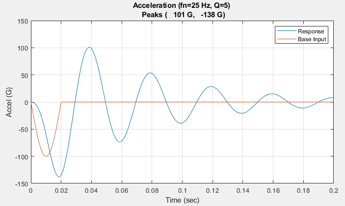
The same example, but with a 100 G half sine acceleration pulse of 0.02 s duration is shown below.
Hope you find this helpful.
-
December 23, 2023 at 11:02 pmSubscriber
Dear Peter,
Thanks a lot for the detailed explanation on the topic.
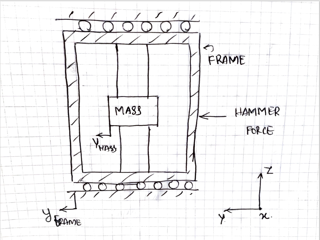
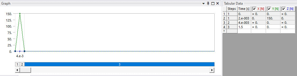
For my task, I am trying to create a finite element model of an existing experimental system. I need to verify the model with already existing experimental results(schematic of the same is attached below). The frame has a mass of around 10 Kg. The mass beam system has aroung 1 kg. The force 150 N for a duration of 4e -3 sec, that I have used here is the impulse force which was used in the experimental analysis. This excitation created a response of the frame, as well as the mass-beam system. The response of the frame was later filtered out to obtain the response of the mass-beam system. I am not aware how to replace this force with an acceleration/ velocity impulse.
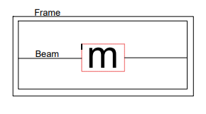
The frame has a particular stiffness (kf) as well as damping(bf) and is free to move in the y direction as shown in the schematic diagram.In the experimental set up, the entire frame is hanging from a support structure by ropes(along the x direction) so that it is free to vibrate along the y direction, along which the force is applied. I am a bit confused as to what boundary condition I have to apply on the frame. I tried frictionless support and elastic support (with a random foundation stiffness) in two different analyses. But the analyses failed. I am relatively new to transient analysis and ansys as such.

-
-
December 24, 2023 at 1:42 amSubscriber
If the frame is hanging from ropes, wouldn't the ropes be along the Z direction (vertical) not along the X direction (horizontal)? If the ropes are along the X direction, they will stretch with the weight of the frame and mass until the Z component of the tension in the ropes equals the weight of the frame and mass.
Let's assume the ropes are vertical and there are 4 ropes coming from the four corners of the top face of the frame: 2 on the left side and 2 on the right side, one each on the near and far side in the X direction. You could apply a Z = 0 constraint on the 4 nodes of the four corners of the top face of the frame.
I suggest you convert your geometry so that the frame and the flexures are all surface bodies so you can mesh them with shell elements and assign a large thickness to the thick frame and the correct thickness for the flexures supporting the mass. The mass can be configured to be a rigid body. Use Fixed Joints to connect the edges of the flexures to the mass and the thick frame. Now you can apply the force profile to a node at the center of the right side face of the thick frame. The structure will vibrate during a Transient Structural solution.
I am interested to hear how you will filter out the response of the thick frame.
Before you run the Transient Structural solution, you should run a Modal analysis to see what freqencies are in this structure.
-
December 24, 2023 at 7:34 amSubscriber
Dear Peter,
Thanks a for the insights. I will try to model the parts as surface bodies, which I need to figure out how.
Meanwhile, the frame is hung along the x direction itself, horizontally. Like a bed hung from its 4 corners, or more precisely like a swing. And we are pusing the swing to find its response and the response of beam mass system attached to it.
To answer you question, i was thinking about exporting the displacement/acceleration probe data to matlab or something and filtering them.
Anyways, I will try to model it as you said and will get back.
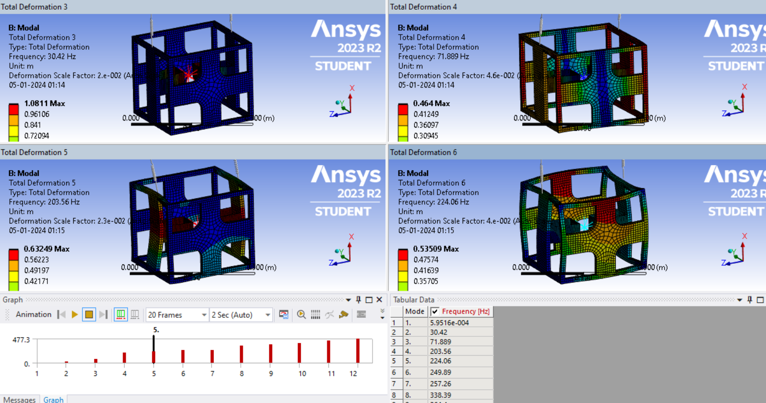
I had conducted the modal analysis for the current model. The fundamental frequency is 25 Hz. As I said, I was just randomly modeling so that just the mass value of the frame and mass matches with that of the experiment , just to find if the beam mass oscillates due to the excitation on the frame.
-
-
December 24, 2023 at 11:58 amSubscriber
In SpaceClaim, on the Prepare tab is the Midsurface button. If you click once on a face and then again to pick the face through the thickness, SC will find all the face pairs that have that thickness and replace the solid with a surface body. That will transfer to Mechanical with the value of thickness that will automatically be assigned to each surface. Do that for the frame and flexures. Follow the directions in my last reply to complete the model.
Nearly horizontal rope will tension the top face of the frame, but let's leave that aside. Later, you could add 4 nearly horizontal springs to ground to more accurately represent the support system. Just use the constraints on the 4 corners for now, but add X = 0 as well as Z = 0 leaving Y free.
In Modal, one of the modes will have the face where the hammer is to strike deforming like a drum head. What is that frequency? That will be helpful to know when choosing time steps for the Transient Structural because that is the mode that the hammer will excite.
-
December 24, 2023 at 8:41 pmSubscriber
Dear Peter,
I created the model in design modeler. I shall try it in SpaceClaim get back.
-
-
December 24, 2023 at 10:27 pmSubscriber
DesignModeller can also create Midsurfaces.
-
December 31, 2023 at 6:53 pmSubscriber
Hello Peter,
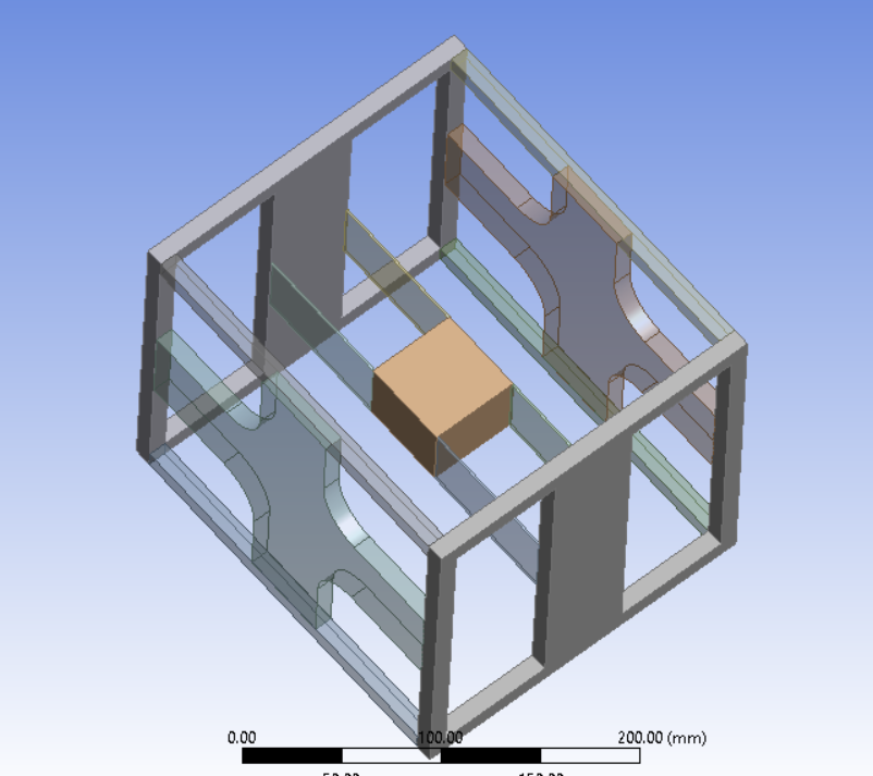
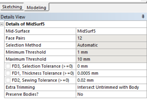
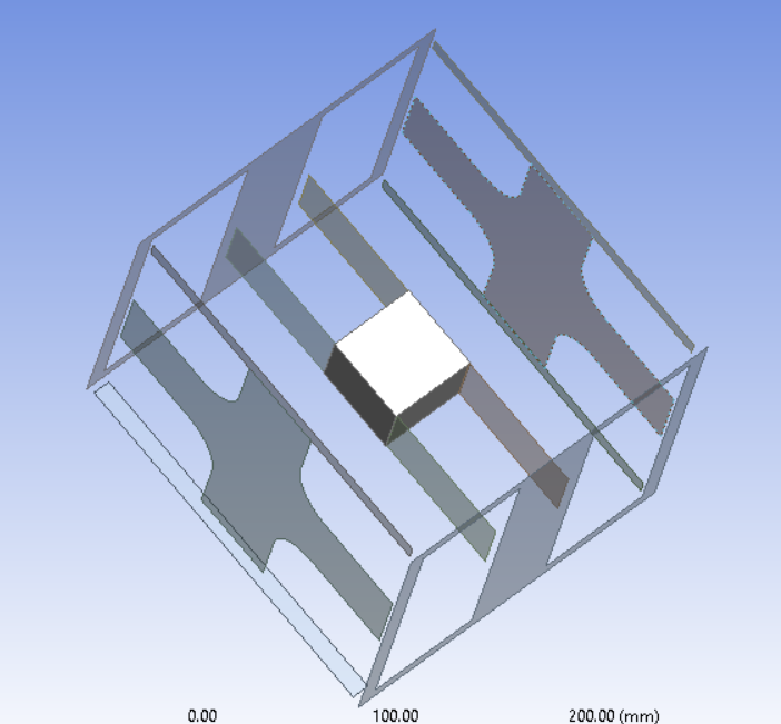
I made a few geometric differences in the model so that it resembles the actual one. I tried applying the mid surfaces using automatic selection with minimum and max threshold as 1 mm and 10 mm respectively. The thickness of the beam is 1.1 mm and that of the frame is 10 mm. I have attached the resulting images. The model after mid surfacing shows disconnected. Is this the right way to do it?
-
-
December 31, 2023 at 8:28 pmSubscriber
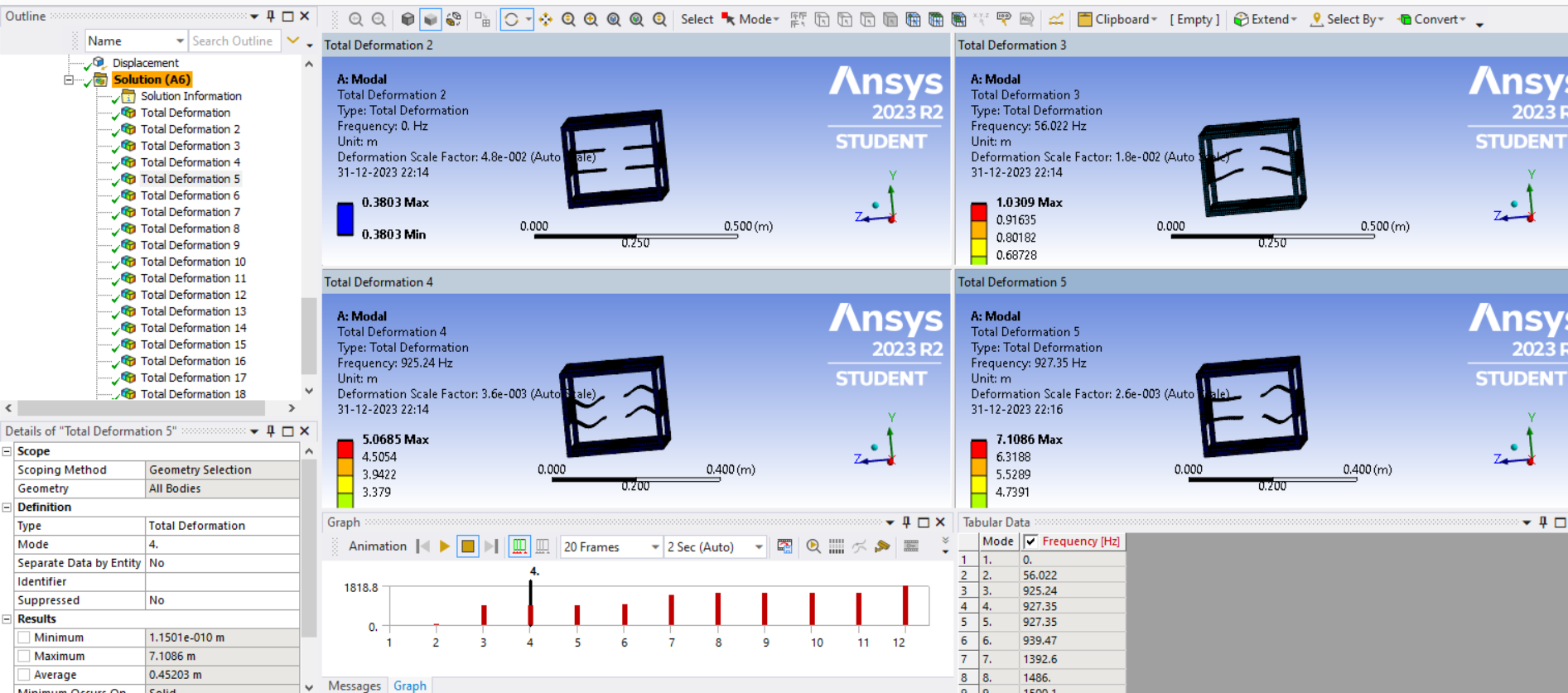
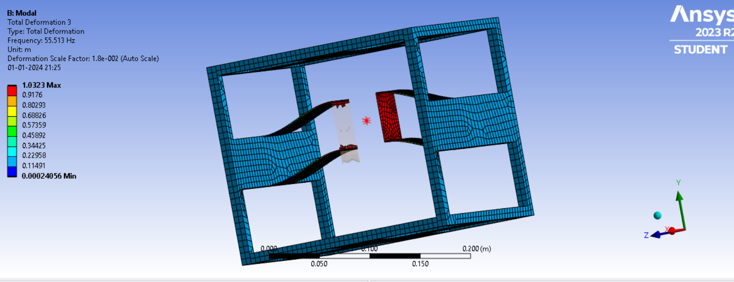
Will it be enough to conduct the modal analysis with frame motion constrained with x and z=0 and y left free?
The results of the analysis is shown (without generating surface bodies). But the frame shows no deformation for the first 12 modes.
-
December 31, 2023 at 10:04 pmSubscriber
It looks like you found a way to deal with the geometry gaps that were created after the midsurface operation was complete.
With the Y direction free, the first mode has a zero frequency which is fine. You can run Transient Structural on this either as MSUP with an prior Modal analysis or as a full Transient with no prior Modal analysis.
For simple X and Z constraints on the corners of top of the frame, the hammer strike will cause the frame to acquire a velocity along the Y axis. The system will travel along the Y axis while the frame and mass oscillate as the time integration happens. If you were to put 4 springs on the corners, there would be some stiffness along the Y axis and the whole system would have a very low first mode frequency of oscillation about the starting point after the hammer strike.
-
December 31, 2023 at 11:25 pmSubscriber
Hi Peter,
The modal analysis was done on the solid model without doing the mid-surface operation. I still don't know how to deal with the gaps. I just tried it on the solid model. It would be great if you could help me. Also, what is the advanatage of surface models over solid models. How do we identify which one to use and when?
-
-
January 1, 2024 at 3:29 pmSubscriber
One advantage of surface models over solid models is computational speed, which is valuable on a Transient model because the matrix equation will be solved thousands of times over the simuation time. One advantage of a MSUP Transient model is computational speed over a Full Transient model. A solid element model will take longer to compute the modes than a shell element model, but that only has to be done once, then the MSUP transient solution will take the same time whether solid or shell until the requested results are processes, then again the solid elements will take longer to convert the MSUP solution back to the nodal results than the shell model.
There are a few ways to deal with the gaps. In Mechanical, Bonded Contact could span the gap and hold the pieces together. Set Use Shell Thickness to Yes. Another approach is to open the surface model in SpaceClaim and pull an edge to the face it should connect with and use the Share button on the Workbench tab to have the meshing software connect the pieces.
-
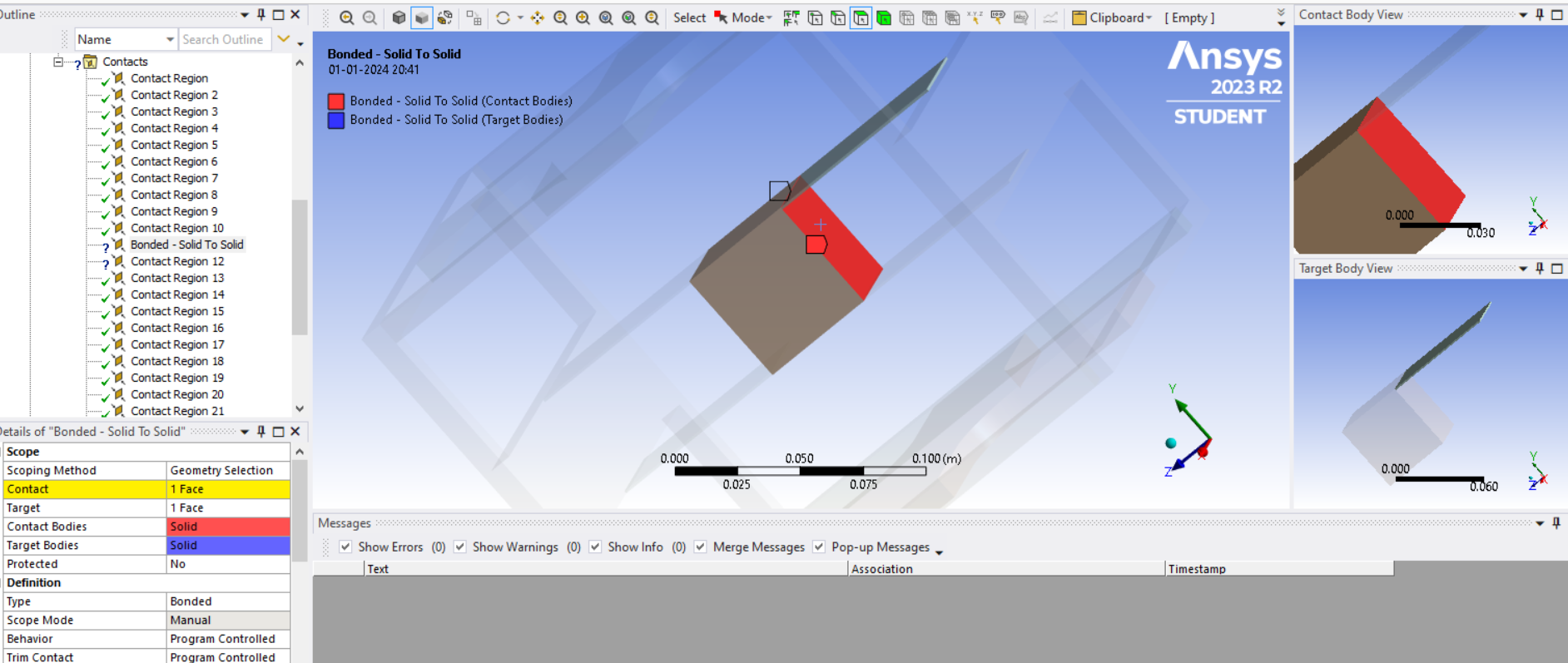
January 1, 2024 at 7:45 pmSubscriber
I encountered another issue while assigning the mass as a rigid body. I am unable to select the face of the mass for contact regions.
Previosly, i deleted those regions and introduced joints there. But I am confused because the '?' is shown only on two of the four beam-mass connections. The other two are automatically connected.
-
-
January 1, 2024 at 8:19 pmSubscriber
Right click on that Bonded Contact and Flip Contact and Target sides. The rigid body must be on the Target side.
-
January 1, 2024 at 8:27 pmSubscriber
Thanks a lot Peter,
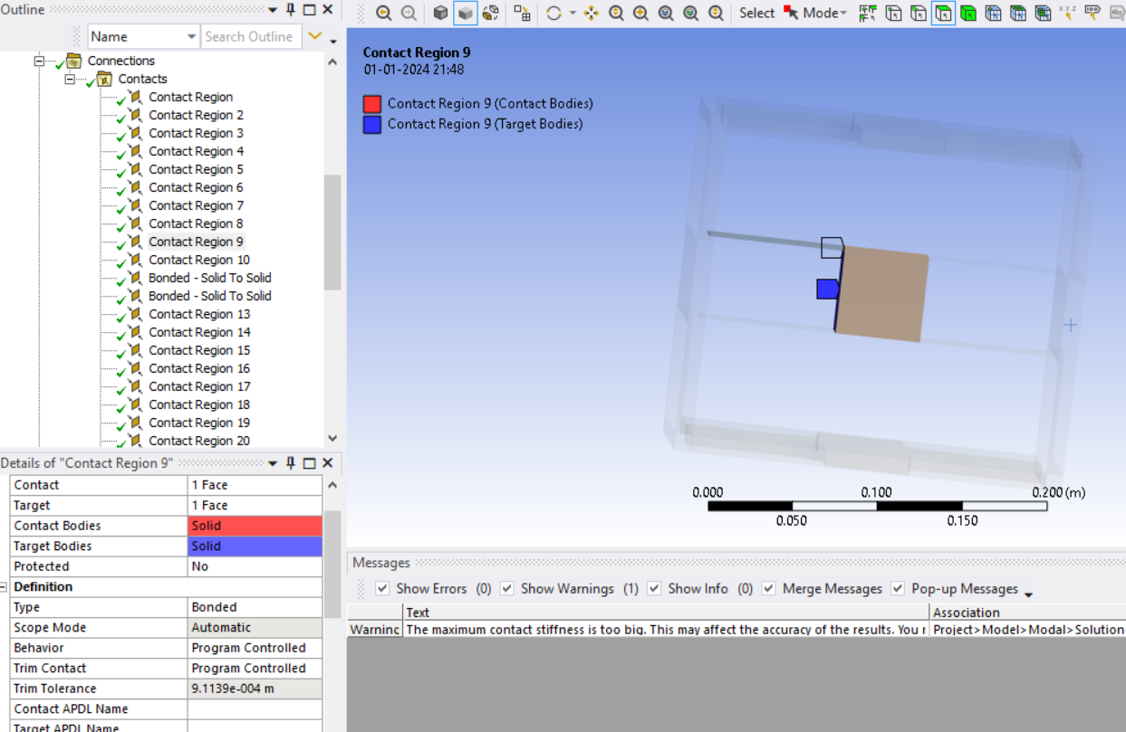
Is there any specific reason that one face of the mass is shown meshed and other one not??
-
-
January 1, 2024 at 8:33 pmSubscriber
Did you pick Face or Edge for the other Bonds? That would explain it.
Does one set of Bonds have a small pinball radius and the other set of bonds have a large pinball radius?
-
January 1, 2024 at 8:46 pmSubscriber
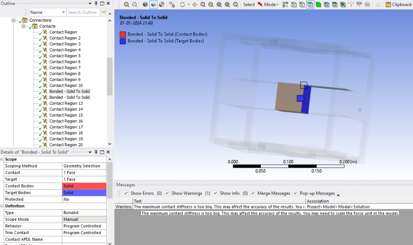
As I said, except for the two connections at the right hand side, everything else was automatically connected. Hence the doubt. I connected with faces. Except for the scope mode, everything else is shown program controlled.
-
-
January 2, 2024 at 1:36 amSubscriber
Scope Mode for one is Automatic and shows a Trim Tolerance while the other is Manual and has no Trim Tolerance. I expect if you make them all the same, you will get the same appearance, but since you are connecting to a rigid body, the difference does not matter.
-
January 3, 2024 at 7:07 pmSubscriber
Hi Peter,
I conducted the transient analysis with the following conditions,
BC:
Displacement at the left and right edges with only Y motion possible
Displacement at the 4 corners of the base (where the force is applied) with only y motion possible
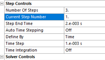
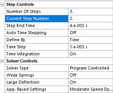
Force of 150 N applied on a node at the base as a 3 step analysis (analysis settings attached)
The analysis was aborted with the following errors.

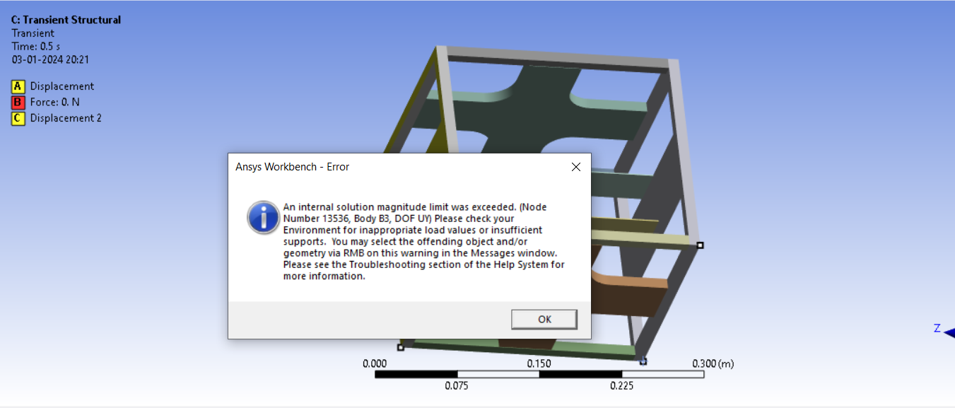
-
-
January 3, 2024 at 9:10 pmSubscriber
Why is Time Integration turned off in Step 1? That is where the force is ramping from 0 to 150 N. Time Integration should be on.
Why is Auto Time Stepping turned off? It will be much easier for the solver to converge if it is turned on and the Minimum Time Step is a small number such as 1e-5 s. The Initial Time Step could be 1e-4 s and the Maximum Time Step could be 1e-3 s.
-
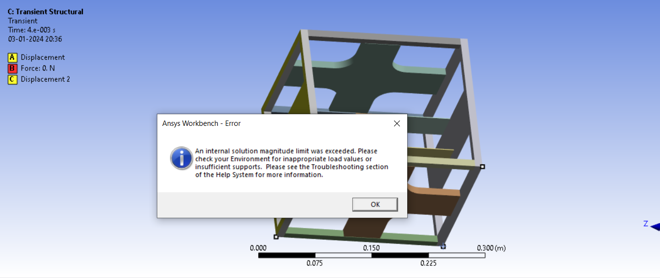
January 3, 2024 at 9:24 pmSubscriber
Still showing error.
-
January 3, 2024 at 9:37 pmSubscriber
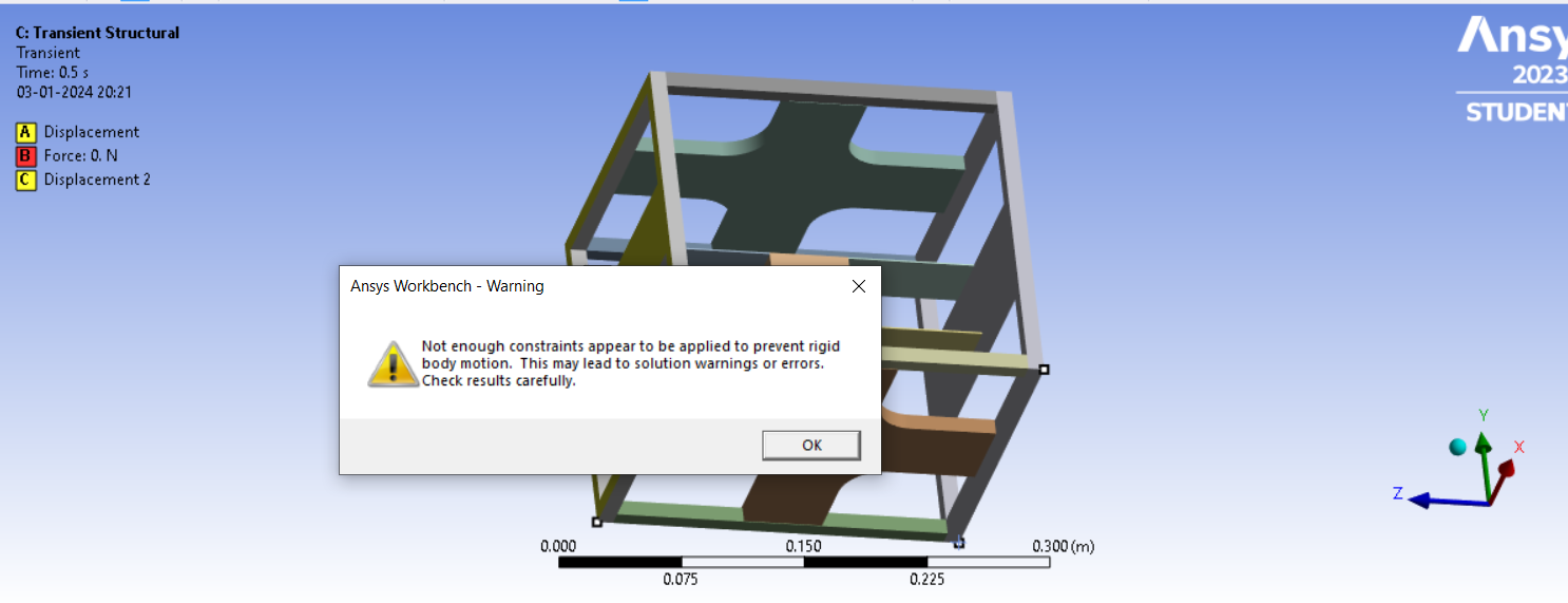
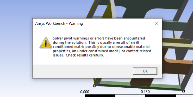
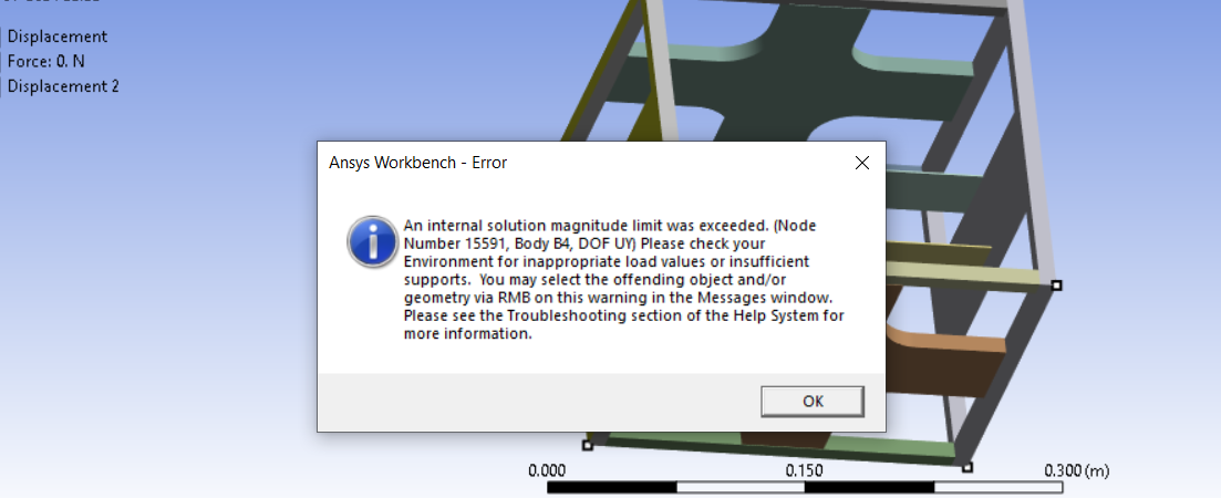
Is there something wrong with boundary condition given? One of the warnings says this.
-
January 4, 2024 at 7:57 pmSubscriber
I tried conducting the analysis by just randomly tried fixing the frame. It got solved without error. But unfortunately that is not the boundary condition that I need. Is it not possible to conduct the analysis with constrained motion?
I guess the Y motion which was given to the frame creates a translational motion along the y direction rather than a vibrational response. As I said, in the experimental rig, the frame is hung with the help of 4 elastic ropes. But, the stiffness or other properties of the rope are unknown. How can i simulate this hanging scenario?
I tried introducing a couple of springs with a random stiffness value. But still the analysis is getting aborted with the same previous error.

-
-
January 4, 2024 at 11:46 pmSubscriber
Does a Modal analysis of this model solve?
-
January 5, 2024 at 12:11 amSubscriber
Yes, modal analysis is successfull in both cases (with and without spring).
-
January 5, 2024 at 12:24 amSubscriber
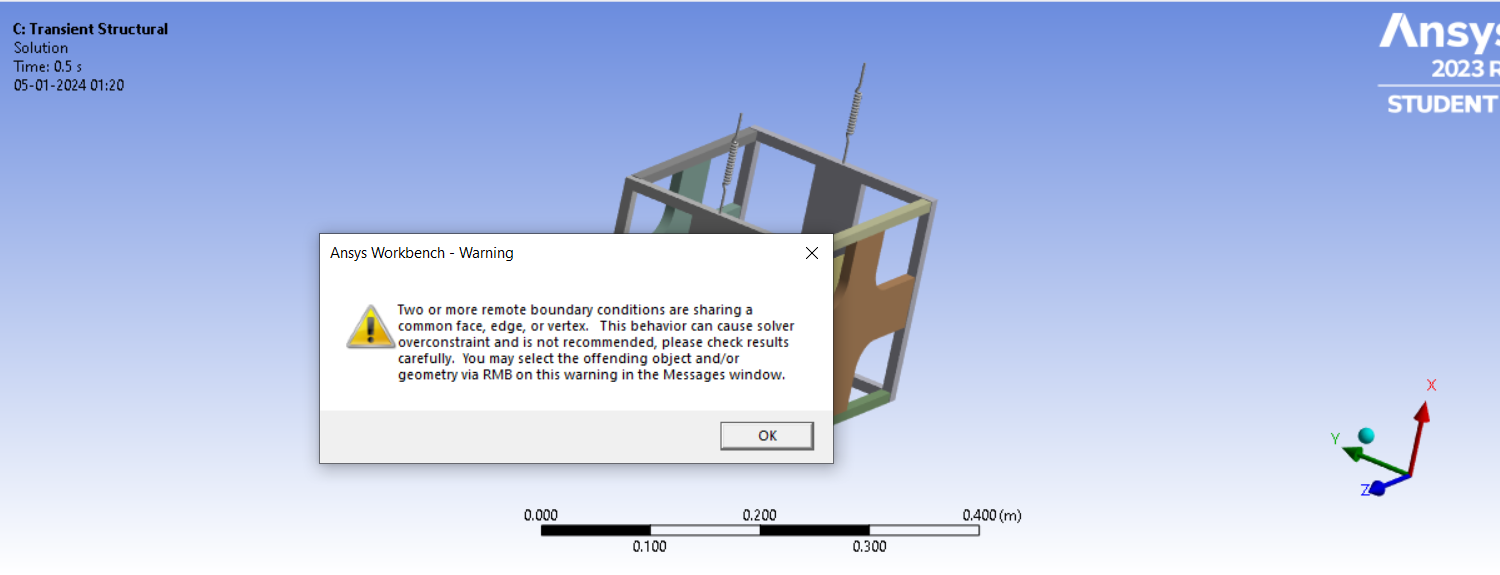
In addition to the previous errors, the transient analysis of the model with springs shows this additional warning.
-
January 7, 2024 at 3:09 pmSubscriber
Hi Peter,
Please help.
-
-
January 5, 2024 at 12:13 pmSubscriber
-
January 5, 2024 at 1:53 pmSubscriber
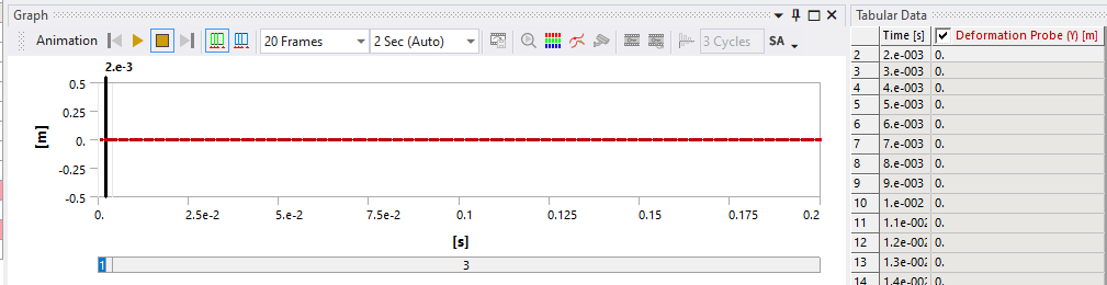
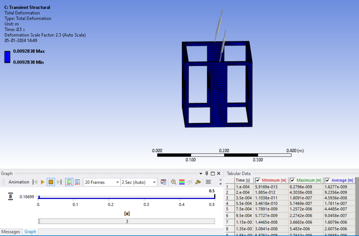
I changed the connection of spring remote attchment to direct and the transient model is showing results with warnings. But the deformation and displacement probes (frame and mass) does not show an oscillatory motion as expected.
-
January 7, 2024 at 11:57 pmSubscriber
Please use File, Archive and create a .wbpz file without results. Upload that file (not the .wpbj file) to a file sharing site such as Google Drive or Jumpshare and put the link in your reply. If you use Google Drive, make the link so that anyone with the link can download the file. I will have a look in the next few days.
-
January 8, 2024 at 8:17 amSubscriber
https://drive.google.com/file/d/1NT5m9-Cr9uTsQzzkD23gOA3j63f5m4dB/view?usp=sharing
Hello Peter,
Thanks for the support. I have uploaded the .wbpz file in the above link.
-
-
January 10, 2024 at 11:48 pmSubscriber
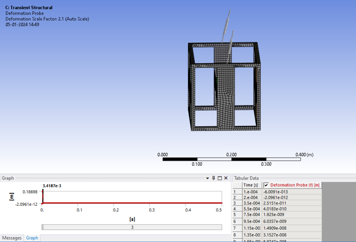
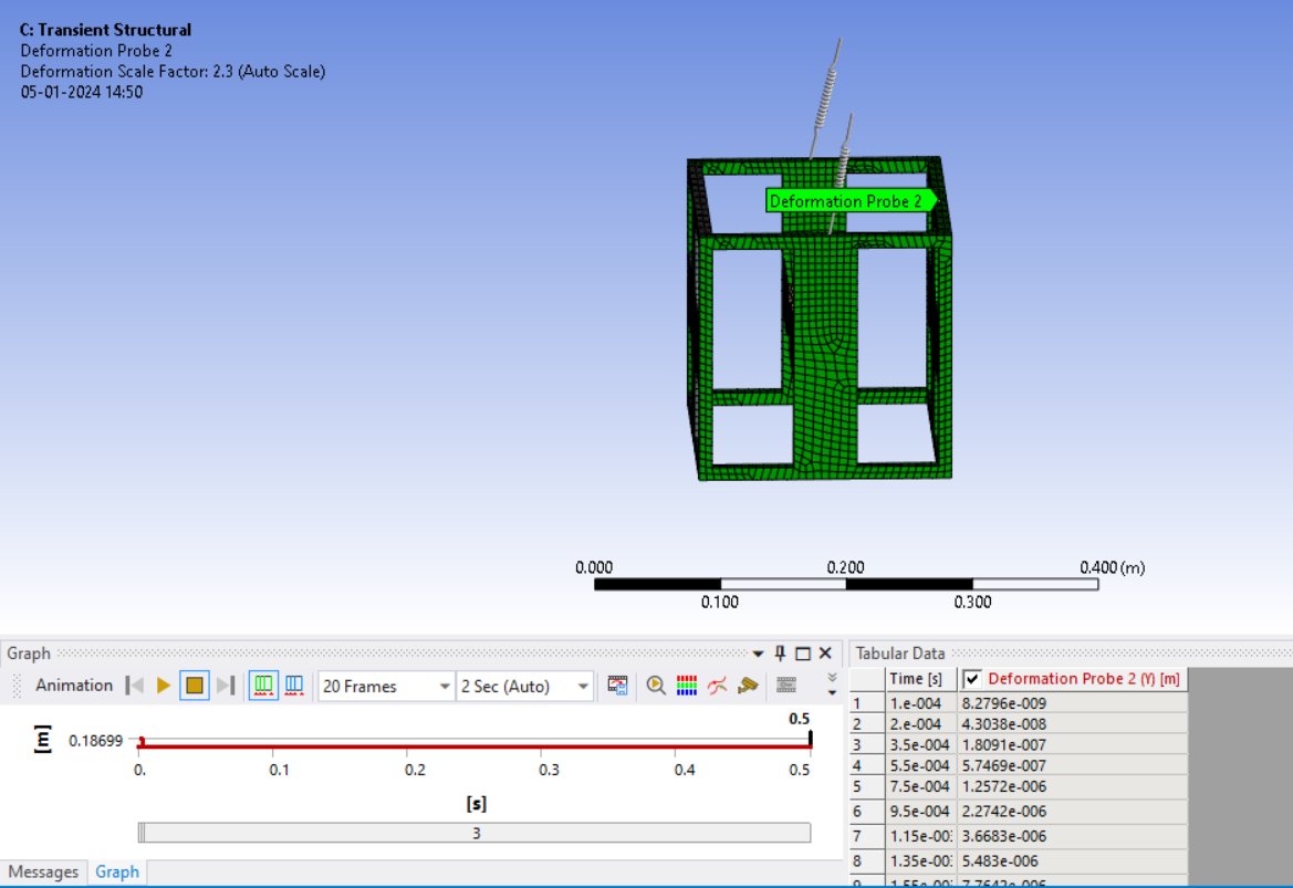
Here is an archive of the beam and shell version of your structure.
After you open the archive, you should clear generated data on the Modal solution and on the Transient solution, then you can solve the Modal and solve the Transient.
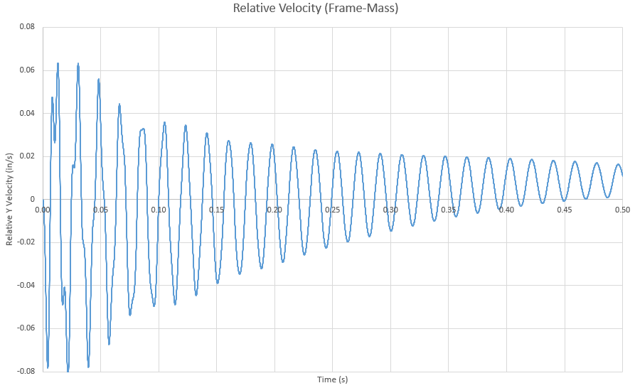
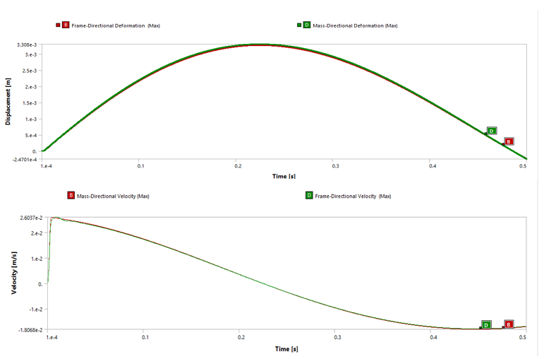
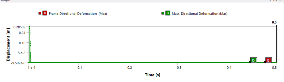
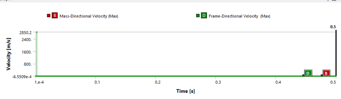
You will see that I requested a directional Y velocity result of a single node on the mass and another result for a single node on the frame. If you copy the tabular data out of each of those results and paste them into Excel, you can plot the relative Y velocity of the frame and mass. It looks like this:
-
January 11, 2024 at 9:05 amSubscriber
Hello Peter,
It is working. Thanks a lot for your time and effort. I have a few questions.
- Can you please tell me what were the mistakes in my model?
- I see that you have modified the geometric model. Will it be possible to obtain the same results in the geometric model that I created? If so, what changes should be made?
- I see the natural frequency values and mode shapes have changed significantly from what I obtained, even though the mass, the materials and the boundary conditions remain the same. What is the reason for that?
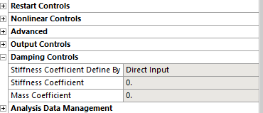
- Can you please explain the damping control given ? Because, ultimately I am supposed to find out the response of the system to different values of damping (damping ratio from 5-30 % applied on the beam mass system) and beam stiffness(by varying the length of the beam). Eventually, I also need to apply an active damping force on the mass by active velocity feedback control force. (schematic attached)
- Which frequency was considered to calculate the time step in the analysis?
- If I need to run this as a full transient analysis instead of MSUP , what boundary conditions and analysis settings should I give?

Hope it is not a trouble. This is my first time working with ansys and I am supposed to work with it for a long time and I don’t know anyone who can help. Once again, thanks a lot for the help.
-
-
January 11, 2024 at 10:17 pmSubscriber
1. One mistake was the springs in your model were not arranged along the Y axis. I changed them to be along the Y axis which caused the first mode to be non-zero.
2. I tried to get your model to run, but could not so I decided to put the work in to convert the geometry to beams and shells. I assigned everything Aluminum. I didn’t check what the material assignments were in your original model, but the beams and shells have the same cross-section and thickness as your original geometry. There were a few minor tweaks to get the edges and vertices to line up.
3. I didn’t spend any time comparing modes from your model to my model. I greatly reduced the number of bonded contacts and joints, so you model may have had extra stiffness where it didn’t belong due to those.
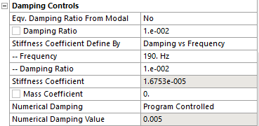
4. I wanted a lightly damped structure that would ring out past 0.5 s so I put in 1% damping ratio for all frequencies, and then I put another 1% damping ratio at 190 Hz because I wanted the damping to increase linearly from low to high frequencies to damp out the high frequency modes more quickly and let the low frequency modes have lower damping.
5. I considered the frequency content of the force pulse, which had a period of 0.008 s or 125 Hz. So a maximum time step would be 1/20 of that or 0.0004 s. The highest mode requested in Modal was a bit higher than 250 Hz or a period of 0.004 s to see that mode properly rendered you would want a maximum time step 1/20 of that or 0.0002 s. You already had 0.0001 s so I kept what you had.
6. You can run my beam and shell model as a Full Transient. All you have to do is delete the link between the Solution cell of Modal and the Setup cell of Transient Structural.
-
January 12, 2024 at 12:40 pmSubscriber
Hello Peter,
Thanks a lot for the detailed explanation. The effort is much appreciated.
Do you have any literature where I can get specific understanding of these things. I have taken ansys courses offered in transient analysis, but that is more of a general approach.
As i said in the above message, I need to introduce various damping values as a damper connected between the mass and a frame. If i model a spring with very low stiffness and required damping value, will it act as a damper?
Is there any other way to introduce damping to the mass-beam part alone?
I tried to carry out a full transient analysis with model. I transfered the dosplacement BC in modal analysis to transient, keeping all other settings the same. It is getting solved, but the rigid motion warning appears and a different displacement pattern appears. The velocity and acceleration also shows the same response. However, the relative values give a damped oscillation.
 What can be done to avoid that?
 -
January 12, 2024 at 1:15 pmSubscriber
You can add a spring between the mass and frame exactly has you have shown. Enter a value for a Longitudinal Damping coefficient only and leave the spring constant at 0. You can also add a Damping coefficient to the springs on the frame. Damping can only be used in a Full Transient, so this only works after you have deleted the link from the Solution cell of Modal into the Setup cell of Transient.
Instead of adding a spring between the mass and frame, you can create a new material in Engineering Data and call it Damped Flexures and apply that material to the flexures. I would have thought that the flexures were made of steel, not aluminum, but just create it with the correct Density and Isotropic Elasticity inputs. Look in the Physical Properties and drag out one or more of the Damping properties: Material Dependent Damping, Damping Factor (alpha) or Damping Factor (beta). Read up on Rayleigh Damping to understand alpha (stiffness) and beta (mass) Damping Factors which create a frequency-dependent Damping Ratio. Constant Structural Damping Coefficient in the Material Dependent Damping property lets you define a constant Damping Ratio that is applied to all frequencies equally.
You can ignore the warning about Rigid Body Motion.
-
January 12, 2024 at 1:26 pmSubscriber
Ok. Another concern I have is on introdcing an active, velocity feedback controlled damping force. In the actual system, a sensor detects the velocity of the moving mass and an associated force is actuated with the help of a gain factor through a voice coil actuator. Can that scenario be simulated with the spring elements attaching the mass and frame (as they also generate velocity dependent damping)?
-
January 13, 2024 at 5:42 pmSubscriber
Hi Peter,
I tried to conduct the full transient analysis on the model. But the results are different. Attaching the msup results and full transient results of the same model.
msup results
full transient
-
January 17, 2024 at 2:22 pmSubscriber
Hello Peter,
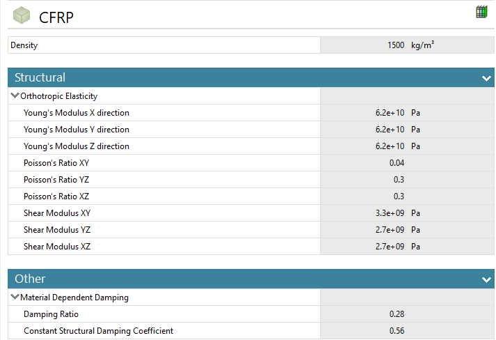
I created a new material for the beams in the system and assigned Damping ratio to it as shown. But it seems the full transient analysis is not considering the damping. Because for different values of material damping I am getting the same results. Do i need to make any chnages in analysis settings. Since I assigned material damping values in the engineering dta, I have not given any other damping in the analysis settings.

-
-
January 12, 2024 at 9:03 pmSubscriber
I expect you can do that. Open a new discussion to ask that specific question for how to create that on a spring/damper element.
-
January 15, 2024 at 1:19 amSubscriber
MSUP Transient is a linear analysis which assumes small deflections.
Full Transient with Large Deflection turned on is a nonlinear analysis and so will not have the same motion as a MSUP analysis.
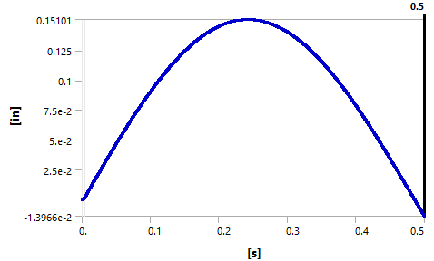
Here is my MSUP Y Displacement of the Mass.
Here is my Full Transient Y Displacement of the Mass
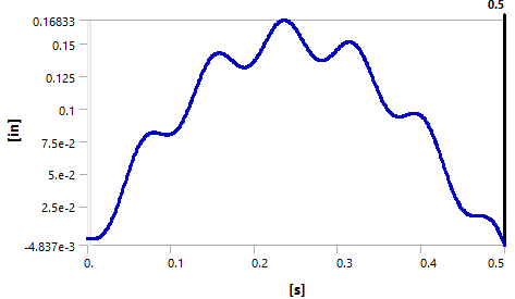
You can see that the results are similar. Your results are completely different so you must have made a mistake.
-
January 15, 2024 at 10:04 amSubscriber
Hi Peter,
It got sorted. When I changed from msup to full, one of the time integration got ‘off’ automatically. Now it is working.
I have one more question rgarding the geometry. As I said, need to conduct the analysis on the model for different lengths of the beam elements attached to the mass. So the model's geometric measurements will change. When I opened the model in spaceclaim, I couldn't find any option to change the lengths of the elements (i had creted the model in design modeler using extrude). How can that be done in spaceclaim?
What all operations in space claim will I have to learn to do that?
-
-
January 17, 2024 at 8:14 pmSubscriber
In SpaceClaim, learn to use the Pull tool and the Move tool. That may allow you to do all of the resizing you need to do.
-
January 18, 2024 at 10:12 amSubscriber
Hello Peter,
Thanks for the response.
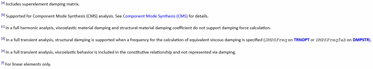
As said eralier, I created a new material for the beams in the system and assigned Damping ratio to it as shown. But it seems the full transient analysis is not considering the damping. Because for different values of material damping I am getting the same results. Do i need to make any chnages in analysis settings. Since I assigned material damping values in the engineering dta, I have not given any other damping in the analysis settings.

-
-
January 18, 2024 at 11:51 amSubscriber
Please review the Ansys Help documents for Damping. In there you will find this page:
https://ansyshelp.ansys.com/account/secured?returnurl=/Views/Secured/corp/v241/en/ans_str/Hlp_G_STR1D.html
I hope you know how to open that URL. Don’t just paste it into any browser. Start Ansys Help from the Start menu or the Ansys Help Menu in Workbench or Mechanical and then paste that URL into the browser that Ansys opened.
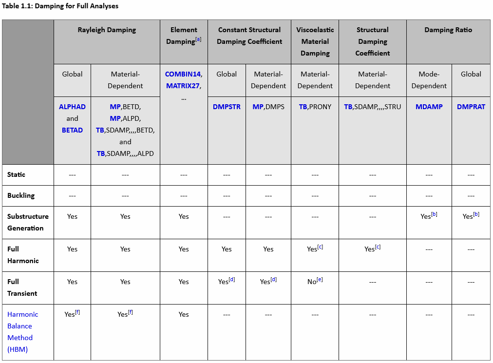
Notice that in the table, Material Dependent Constant Structural Damping is supported.
Pay attention to node [d]. Did you specify a frequency for the structural damping? This is required. However, in Workbench Engineering Data, there is no entry for a frequency.
If this seems odd, you could create a New Discussion to ask about it.
Read the Ansys Help page for the TRNOPT command. https://ansyshelp.ansys.com/account/secured?returnurl=/Views/Secured/corp/v241/en/ans_cmd/Hlp_C_TRNOPT.html
Notice that if you use Rayleigh Damping, you don’t need to specify the frequency. This method of damping can also be applied in a Material Dependent way.
Notice that Material Dependent Structural Damping is not used in a Full Analysis and that this is separate from Material Dependent Constant Structural Damping which is supported if you provide a frequency.
Notice that Material Dependent Damping Ratio is not used in a Full Analysis, so your 0.28 value is not used.
You will find another table where some damping that is not used in Full Transient is used in MSUP Transient.
Unfortunately, Damping is a complex area with a multitude of special cases so you really have to study the tables in Ansys Help to get it right.
-
January 18, 2024 at 2:43 pmSubscriber
Hello Peter,
Thanks a lot for the information.
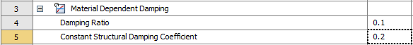
Unfortunately, both the links are not found in the ansys help page. I guess there is some issue with the site.
-
-
January 18, 2024 at 3:47 pmSubscriber
Do not paste the URL provided into the Search field of Ansys Help, paste it into the Address field of the browser at the top of the window.
-
January 22, 2024 at 2:01 pmSubscriber
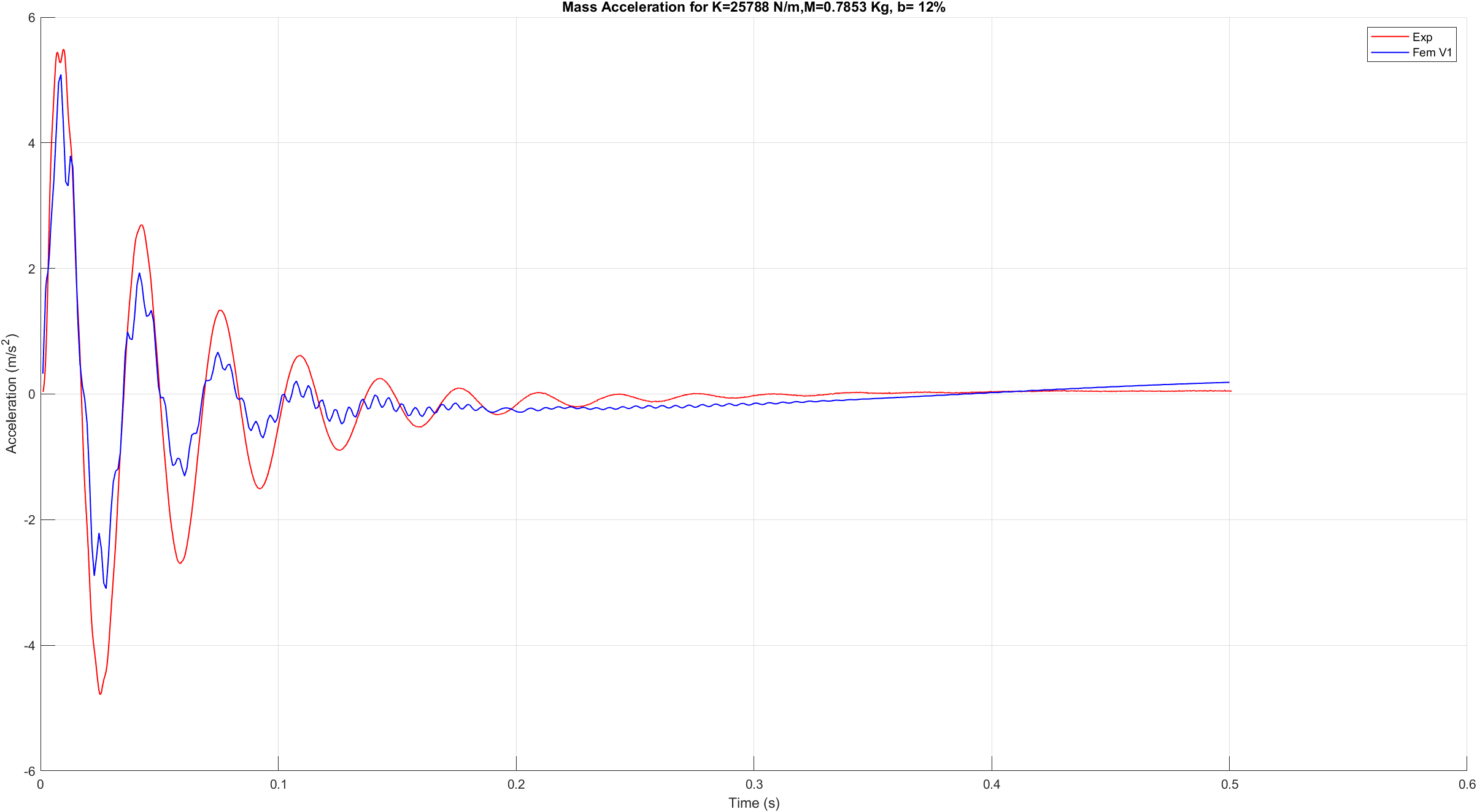
Hello Peter,
I was verifying the model with the experimental results. The blue plot shows the FE results and red one shows experimental response of the mass for a particular damping which i have applied through the spring attached between mass and frame. What might be the reason for the small vibrations presents on the FE response. Also, while verifying the frame acceleration, I found that different points on the frame are giving different accelerations. Since the body is moving as a unit, shouldn't the acceleration be same at all points??
(I am using the solid model instead of the shell model as the natural frequency of the shell model was not matching with the actual value)
-
-
January 29, 2024 at 9:26 amSubscriber
Hello Peter,
I have a doubt regarding the natural frequencies of the system. Suppose when I am modeling this system analytically, I consider the mass at the center as the first mass and the whole frame as the second mass, making it a 2 degree of freedom system. Corresponsing calulations will give two natural frequencies as well, based on which further calculations can be done. In FE analysis, how is possible to extract which modal frequency corresponds to which part, mass part or the frame.
Precisely, what does the different modal frequency values in the FE modal analysis tell us. Which of those should be considered and which all should be neglected?
-
January 29, 2024 at 7:17 pmSubscriber
After a Modal analysis has solved, there is a Mass Participation Factor table available for inspection.
Review Lesson 4 for more information and take the whole Modal Analysis course if you haven't already.
-
- The topic ‘Response of a system to an excitation on the frame’ is closed to new replies.


-
peteroznewman
 5824
5824 -
scabo
 1906
1906 -
Dennis Chen
 1420
1420 -
javat33489
 1305
1305 -
Shyam Prasad V Atri
1021


© 2026 Copyright ANSYS, Inc. All rights reserved.
