-
-
September 10, 2024 at 5:10 pm
agyaw1
SubscriberHi Everyone,
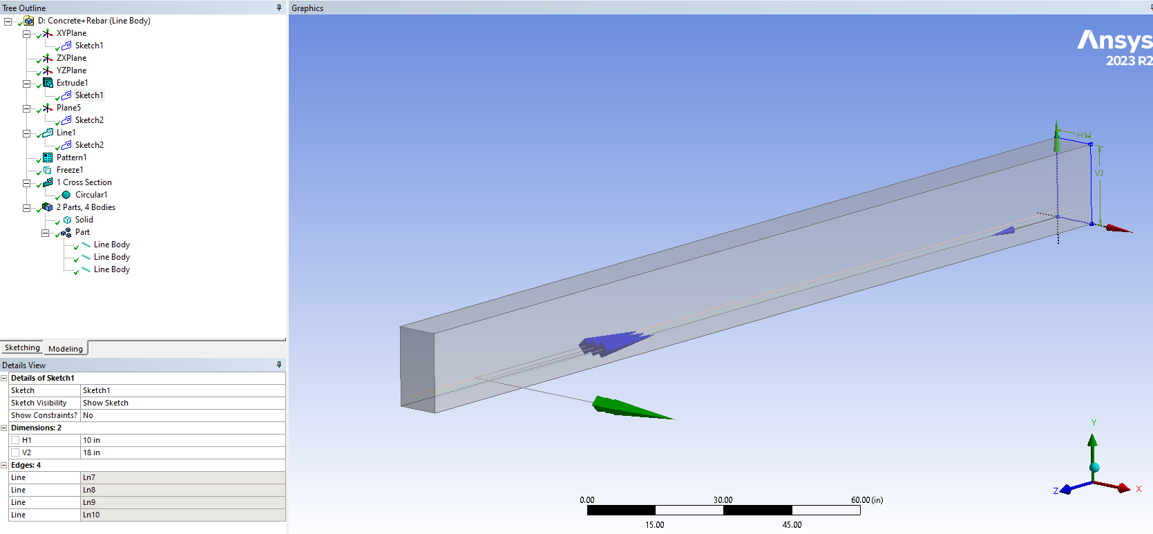
I am modeling a large concrete structure (40 ft long, 20 ft deep, and 3 ft thick) with reinforcement. Before modeling the exact structure, I created a test beam (10 in wide by 18 in deep) with three #9 rebars. I defined it as reinforcement as line body and assigned the cross-section, but after meshing, I cannot see the rebar and concrete sharing mesh nodes and contact surfaces. Can I trust the results of the beam model? Is it necessary for the rebar and concrete to share nodes during meshing?
Data after analysis are close enough but i need confirmation to model real structure.
-
September 10, 2024 at 5:31 pm
ErKo
Ansys EmployeeUsing reinforcement Model type is fine for rebar and the way to do it (no need to have shared nodes, or contacts).
Finally for a whole workflow and set up, see a tutroial I made some time ago:
https://innovationspace.ansys.com/forum/forums/topic/how-can-we-model-failure-in-reinforced-concrete-rc-slabs/
-
September 10, 2024 at 6:05 pm
agyaw1
SubscriberHi Erik,
Thankyou for your conformation regarding rebar. but one more question Just like REINF264 element, SOLID185 is used as default? If not How to use SOLID 185 element?
Regards,
Ashok
-
September 11, 2024 at 6:08 am
ErKo
Ansys EmployeeHi
We do not have to use hex8 solid185, the default is hex20 solid186 which you use - I just showed it in my tutorial because it helps when models are large (less dof and nodes with hex8 solid185).
If you want to use it still see image 7 or slide 8 called slab for the settings (El. Order = Linear)
All the best
Erik
-
September 14, 2024 at 6:18 pm
agyaw1
SubscriberHi,
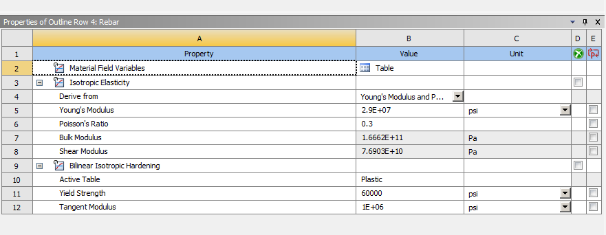
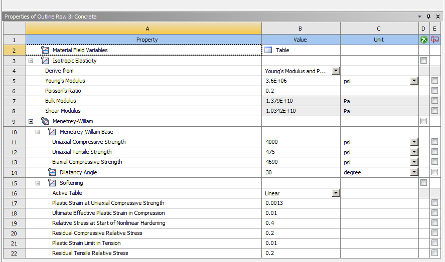
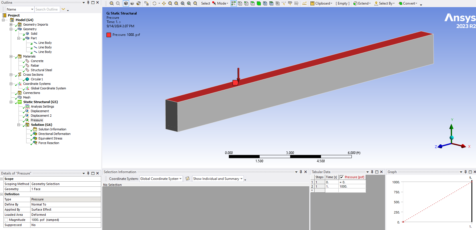
Here I mentioned all the images of the model. Concrete is cracked in this situation, so the result doesn't match the theory. I saw your tutorial and inserted the command in the solution, but there wasn’t any change in the answer. Specifically, can you help me in which section I need to change or add a command to model a reinforced concrete beam? I am trying it in a beam model, but my actual structure is different. Thank you.
Ashok
-
- You must be logged in to reply to this topic.


-
4683
-
1565
-
1386
-
1242
-
1021

© 2025 Copyright ANSYS, Inc. All rights reserved.


