
-
-
October 5, 2020 at 7:10 pm
MAMIN219
SubscriberAfter your suggestions I am stating new discussion here,
Respected sir @peteroznewman
Thank you for your wonderful suggestion on 'PTC Mathcad Prime',
1)Sir actually we are trying to shift the tool 0.7mm towards the workpiece so that we don't have to give the depth of cut (that is the x -component ) , but we could not make it . So if possible can you shift the tool 0.7mm and send us back the file by making the changes .
Sir these is my final file with appropriate boundary condition
That is depth of cut =0.7 mm
Feed = 0.4 mm per revolution
Rpm = 350
Workpiece dia = 23 mm
End time = 1.364 as per your previous calculation
Similarly cutting velocity = as per your calculation
Angular velocity = as per your calculation
Since we need to have 50 revolution which means 50*360 = 18000 ( please check that it is right )
NOTE: Please check my Remote displacement all data and also check global coordinate along with all the selection of faces which i have selected in below ansys 2020 R1.
So sir please take a look at my file and let me know if i have made any mistake soo that i can finally start with my simulation as soon as possible
October 6, 2020 at 12:38 ampeteroznewman
SubscriberPlease learn how to use the Move tool in SpaceClaim.nOctober 6, 2020 at 1:38 amSubscriberThank You sir for your replynSir, Have you opened my file which is ANSYS 2020 R1. nAre there any mistake to choosing any data and selection of faces/ geometry and all of my calculationsnPlease check my Remote displacement all data and also check global coordinate along with all the selection of faces which I have selected in my previous Discussion nPlease give your valuable feedback on my previous query so that I can put my simulationThank you nMihir AmiOctober 6, 2020 at 1:48 amSubscriberIt is a mistake to select the whole workpiece body for the remote displacement, just use the back face.nIt is a mistake to select the whole tool body for the displacement, because that prevents deformation in the tool. Hold the tool on faces where it is supported by the machine that clamps on the tool. You will need to make some faces for that, or cut the tool off short and hold the back face of a shorter tool.nOctober 6, 2020 at 2:27 amSubscriberThank you for your answer Sir Now I am understand the logic behind the selection of faces.nn1) I have mentioned global coordinate for remote displacement and mention for 50 revolution and 18000 as z components. This all calculations are correct? n2) Sir in your file you have selected coordinate system for cylinder and coordinate system 2 for Tool but you cant mention in displacement of remote displacement what is reason behind that please highlight more in thatn 3)Sir this your file and you have selected global coordinate for this .why you have not applied coordinate system 2 for tool is there any specific reason for that? nAccording to your guidance i have selected back faces of workpiece n
 In that above fig in have mentioned global coordinate for remote displacement is correct or any changes in this?.nn
October 6, 2020 at 10:27 amSubscriberFor Displacements,, any cartesian coordinate system that points in the right direction can be used.nFor Remote Displacements, any cartesian coordinate system can be used. What is important is the coordinates in the remote displacement, because that is the point where the object rotates about.nWhat is coordinate system 2 for? I don't need that.nPlease mark the other discussion with an Accepted Answer.nOctober 8, 2020 at 10:55 amSubscriber
In that above fig in have mentioned global coordinate for remote displacement is correct or any changes in this?.nn
October 6, 2020 at 10:27 amSubscriberFor Displacements,, any cartesian coordinate system that points in the right direction can be used.nFor Remote Displacements, any cartesian coordinate system can be used. What is important is the coordinates in the remote displacement, because that is the point where the object rotates about.nWhat is coordinate system 2 for? I don't need that.nPlease mark the other discussion with an Accepted Answer.nOctober 8, 2020 at 10:55 amSubscriber Respected sirnActually I am little bit confused with your above calculationsnnIn this Feed rate =Feed ×RPMnWhere Feed =0.4mm/revolution and RPM=350 revolution per minute nSo according to this I am getting feed rate 2.33mm/secnAnd if i use the same formula and convert RPM to rad/sec that is 36.65 rad/sec then i get the same answer which you have shared that is 14.661mm/secnnSo sir what can i do nWill i take RPM Or value of rad/sec . Please clarify my doubt.Thank you nMihir Aminn
October 8, 2020 at 8:17 pm
Respected sirnActually I am little bit confused with your above calculationsnnIn this Feed rate =Feed ×RPMnWhere Feed =0.4mm/revolution and RPM=350 revolution per minute nSo according to this I am getting feed rate 2.33mm/secnAnd if i use the same formula and convert RPM to rad/sec that is 36.65 rad/sec then i get the same answer which you have shared that is 14.661mm/secnnSo sir what can i do nWill i take RPM Or value of rad/sec . Please clarify my doubt.Thank you nMihir Aminn
October 8, 2020 at 8:17 pmNachiket_0301
Subscriber Respected sir,nActually i am bit confuced with calculation which you share with nFeed rate = feed*rpmnFeed = 0.4 mm per revolution nRpm = 350rpmnAccording above eqaution i get 2.33 mm/sec but here i use rpm =5.833 revolution per sec.nAnd i use same formula and convert rpm into rad/sec i get same ans which you share with 14.661 mm/secnSo sir i have to use rpm in the formula or rad/secnPln
October 8, 2020 at 8:18 pm
Respected sir,nActually i am bit confuced with calculation which you share with nFeed rate = feed*rpmnFeed = 0.4 mm per revolution nRpm = 350rpmnAccording above eqaution i get 2.33 mm/sec but here i use rpm =5.833 revolution per sec.nAnd i use same formula and convert rpm into rad/sec i get same ans which you share with 14.661 mm/secnSo sir i have to use rpm in the formula or rad/secnPln
October 8, 2020 at 8:18 pmKp_9079
Subscriber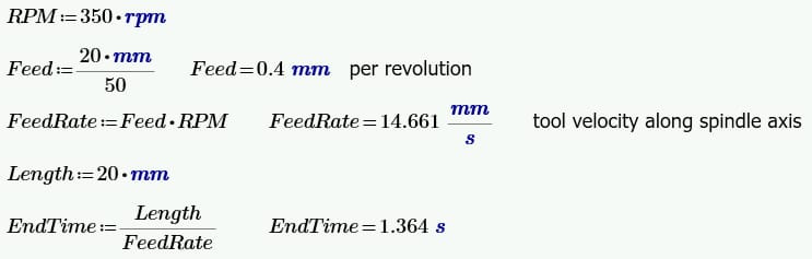 Respected sir nActually i am bit confused with calculation which you shared with nwhere nfeed rate = feed *rpm, where feed = 0.4mm/revolution and rpm =350 nso according i am getting feed rate to be 2.33 mm/sec nAnd if i use the same formula and convert rpm to rad/sec that is 36.63 rad/sec then i get the same ans which you shared that is 14.661 mm/sec nso sir i have to use rpm in the formula or rad/secnpl n
October 9, 2020 at 3:27 amSubscriberHave you gone through our pervious discussion ? nSir has cleared my most of doubt with very great and effective manner which will be helpful for everyone. I am thankful for providing clear concept herenUnfortunately We all are facing the same doubt nDont worry our doubts will get cleared ? byOctober 11, 2020 at 2:56 amSubscriberplease Solve our query as soon possible so that we will further simulate for better understand and enhance our skillsnThank you sirnMihir AminnOctober 11, 2020 at 3:43 amSubscribernRPM is the name of a variable. In hindsight, a better name would be AV for angular velocity, to avoid the confusion between the variable name and the unit name.nAngular velocity can be measured in rad/sec or revolutions per minute (rpm) or revolutions per second. The value of RPM is 350 rpm or 36.63 rad/sec.nI created a new variable called RPS for revolutions per second.nSee if the following correctly calculates the values you need.n
Respected sir nActually i am bit confused with calculation which you shared with nwhere nfeed rate = feed *rpm, where feed = 0.4mm/revolution and rpm =350 nso according i am getting feed rate to be 2.33 mm/sec nAnd if i use the same formula and convert rpm to rad/sec that is 36.63 rad/sec then i get the same ans which you shared that is 14.661 mm/sec nso sir i have to use rpm in the formula or rad/secnpl n
October 9, 2020 at 3:27 amSubscriberHave you gone through our pervious discussion ? nSir has cleared my most of doubt with very great and effective manner which will be helpful for everyone. I am thankful for providing clear concept herenUnfortunately We all are facing the same doubt nDont worry our doubts will get cleared ? byOctober 11, 2020 at 2:56 amSubscriberplease Solve our query as soon possible so that we will further simulate for better understand and enhance our skillsnThank you sirnMihir AminnOctober 11, 2020 at 3:43 amSubscribernRPM is the name of a variable. In hindsight, a better name would be AV for angular velocity, to avoid the confusion between the variable name and the unit name.nAngular velocity can be measured in rad/sec or revolutions per minute (rpm) or revolutions per second. The value of RPM is 350 rpm or 36.63 rad/sec.nI created a new variable called RPS for revolutions per second.nSee if the following correctly calculates the values you need.n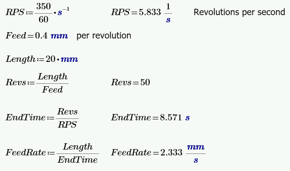 October 11, 2020 at 10:34 amSubscriberThank you sir nactually i am also doing the same analysis nBut when i started the simulation for tool travel for 2mm then it was showing 3000 hours for the simulation to complete nand after 1hour energy error occured nSo is there any other method that can reduce the simulation time to approximately 3-4 days and still i get the accurate real result . nhow can i apply mass scaling or time scaling in these simulation ?.October 11, 2020 at 5:21 pmSubscriberUse the Mesh Metric of Characteristic Length (CL). Locate the element with the minimum CL. That element is controlling the maximum time step, which controls the elapsed time for the simulation. If it is the case where that element is not one being cut by the tool, revise the mesh to make the minimum CL element much closer to the elements being cut. Double the minimum CL and you can expect to cut the elapsed time in half.nIf you increase the density of the element by a factor of four, you can expect to cut the elapsed time in half. nThese two factors and the Young's Modulus combine in an equation to compute the maximum time step. Mass scaling is an artificial (numerical) mechanism for increasing the CFL (Courant-Friedrichs-Levy) timestep of individual elements that govern the maximum allowed timestep of explicit transient dynamic solutions in Autodyn. Increasing the timestep has the obvious benefit of reducing the number of cycles required to run a simulation to a given point in time. Educated use of this option can therefore result in significant improvements in efficiency.nRead the ANSYS help page on Mass Scaling. nArrayTo open the link above, follow these directions.nTo open the link above, follow these directions.nOctober 12, 2020 at 5:09 pmSubscriberThank you so much sir nHowever, I am a beginner nSo how Can i locate Element with Minimum Mesh metric characteristic length ? nit will be true if i Double the value of mesh metric CL , even though it is located where it is cut by the tool ?October 13, 2020 at 12:08 pmSubscriberThis video will teach you how to use the Mesh Metrics tool. The Characteristic Length metric is at the bottom of the list and is not shown in this video.nOctober 14, 2020 at 9:27 pmSubscriberPlease choose a reply to mark as the Accepted Answer and open a New Discussion for any new questions.nOctober 16, 2020 at 10:07 amSubscribernYes accepted answer sir.nThanks for always answer me for my simulation.nI have some doubt so now i will start new conversationnOctober 19, 2020 at 12:05 amSubscriberArray nYou need to click a link below one of my replies to set this discussion as solved. It used to be called Is Solution. You can see some other posts have an Accepted AnswernYou have not done that yet.nOctober 19, 2020 at 3:58 pmSubscriberYes Sir nI have calculated the parameters for 2mm tool travel. In my simulation I have changed mesh and exported from hypermesh. According to our last discussion we have calculated all the things and gave all the parameters according to your guidance, our workpiece is rotating but still the tool didn't travel. Here I'm attaching a 19.2 file, please check it as soon as possible.nnOctober 19, 2020 at 5:10 pmSubscriberThe tool did travel 2 mm.nThe problem is the tool is 6,802.3 mm wide so moving 2 mm is not easy to see. You can measure the distance between vertices and the measurement shows up on the bottom of the window.n
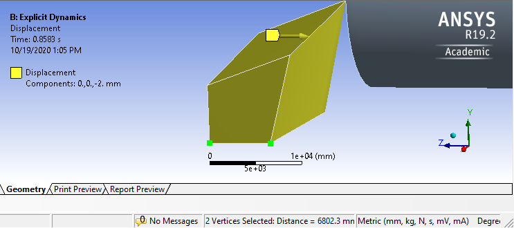 Please mark an answer as accepted and open a New Discussion to ask new questions. This discussion has become too long.n
October 19, 2020 at 6:55 pmSubscriberThank you for your replynSir I want to clarify my some doubt the I will start new discussion. n1) My mesh is perfect or need some change? n2) I have also tried 2-3 approach but sometimes workpiece is rotating as well as some horizontal movement which I have observed. nAnd I am not getting proper turning effect and temperature change in my simulation nCan you please tell what can I do to get turning operation along with nearly appropriate temperatures change. nPlease answer me as soon as possible and please tell regarding meshOctober 19, 2020 at 7:00 pmSubscriberI have changed tool geometry because in our previous simulation hourglass effect is observed and tool is also touch not single point cutting tool at starting whole edge is in contact nSo new geometry is better than first and exported mesh (which is hexahedral from Hypermesh is good or need to change) .nPlease more highlight this question for better understanding. nPlease answer my question as soon possiblennThank younMihir AminnOctober 19, 2020 at 9:09 pmSubscribernYou opened four discussions. I have responded in all of them. You have not marked any with an accepted answer, though my responses seem to answer the original questions.n
Please mark an answer as accepted and open a New Discussion to ask new questions. This discussion has become too long.n
October 19, 2020 at 6:55 pmSubscriberThank you for your replynSir I want to clarify my some doubt the I will start new discussion. n1) My mesh is perfect or need some change? n2) I have also tried 2-3 approach but sometimes workpiece is rotating as well as some horizontal movement which I have observed. nAnd I am not getting proper turning effect and temperature change in my simulation nCan you please tell what can I do to get turning operation along with nearly appropriate temperatures change. nPlease answer me as soon as possible and please tell regarding meshOctober 19, 2020 at 7:00 pmSubscriberI have changed tool geometry because in our previous simulation hourglass effect is observed and tool is also touch not single point cutting tool at starting whole edge is in contact nSo new geometry is better than first and exported mesh (which is hexahedral from Hypermesh is good or need to change) .nPlease more highlight this question for better understanding. nPlease answer my question as soon possiblennThank younMihir AminnOctober 19, 2020 at 9:09 pmSubscribernYou opened four discussions. I have responded in all of them. You have not marked any with an accepted answer, though my responses seem to answer the original questions.n You just keep asking new questions on a different topic. This discussion is already on the second page and is too long. The original question was on speeds and feeds. I asked you to open a new discussion. You have not done that. I am not responding to any more questions until you mark these overly long discussions with an accepted answer.n
October 20, 2020 at 3:34 amSubscriberSorry for inconvenience,nbut sir actually I can't able to find any link that's why i haven't done 'accepeted answer' Otherwise I did it. Can you please send required step where i can put accepted answer .nonce again sorry for inconvenience, Please forgive me and give me step of this I will do itOctober 20, 2020 at 8:40 am
You just keep asking new questions on a different topic. This discussion is already on the second page and is too long. The original question was on speeds and feeds. I asked you to open a new discussion. You have not done that. I am not responding to any more questions until you mark these overly long discussions with an accepted answer.n
October 20, 2020 at 3:34 amSubscriberSorry for inconvenience,nbut sir actually I can't able to find any link that's why i haven't done 'accepeted answer' Otherwise I did it. Can you please send required step where i can put accepted answer .nonce again sorry for inconvenience, Please forgive me and give me step of this I will do itOctober 20, 2020 at 8:40 amRob
Forum ModeratorArray it should either be a line at the bottom of Peter's post or under the menu on the cog icon on his post answering your question. I can't see either so it may be broken, or as Mod I may not see that option. Re Array's comment, please keep questions to the point and then log a new thread for a new question. nOctober 20, 2020 at 1:14 pmSubscriberYes sir I have tried but not getting this nbut I have posted this things question section of feedback in ansys and sir has responded on my postn in that there is question asked that did you get it and I have selected YES then this marks as accepted answer.n
Viewing 26 reply threads
in that there is question asked that did you get it and I have selected YES then this marks as accepted answer.n
Viewing 26 reply threads- The topic ‘Regarding previous turning operation and checking of parameter in ANSYS 2020 R1 file’ is closed to new replies.
Innovation Space Trending discussions
 Top Contributors
-
peteroznewman
 5824
5824 -
scabo
 1906
1906 -
Dennis Chen
 1420
1420 -
javat33489
 1305
1305 -
Shyam Prasad V Atri
1021
Top Rated Tags
© 2026 Copyright ANSYS, Inc. All rights reserved.
Ansys does not support the usage of unauthorized Ansys software. Please visit www.ansys.com to obtain an official distribution.
-
Ansys Assistant will be unavailable on the Learning Forum starting January 30. An upgraded version is coming soon. We apologize for any inconvenience and appreciate your patience. Stay tuned for updates.


