-
-
October 4, 2021 at 5:07 am
Sumit_Kumar
SubscriberMy simulation needs a fluid to be prefilled and then the other fluids will be added so as to observe the profile they form. So is it possible to initialize a pre filled fluid in fluent before running the simulation.
I'm very new to this software, so do let me know as I have searched a lot for this.
October 4, 2021 at 6:43 amaitor.amatriain
SubscriberYes. You only need to set the value of volume fraction in the Initialization panel.
October 5, 2021 at 11:24 amSumit_Kumar
SubscriberMy geometry is not a hollow geometry, hence, it is not possible to define a fluid domain in designmodeller. So when I set the value of volume fraction, how do i ensure that it applies to the entire geometry?
It is a simple T geometry with an inlet for the fluid simulation and there are no outlets (experimentally, the setup is sealed in the outlets)
October 5, 2021 at 11:30 amSumit_Kumar
SubscriberAlso another doubt, where can I change the volume fraction of the fluid. Should I use multiphase vof and one phase. after that i set the volume fraction as 1?
October 5, 2021 at 1:20 pmaitor.amatriain
SubscriberIn the initialization panel, I guess that you can select the option "all-zones" in the option named "Compute from"
The initial value is set in the initialization panel, while the boundary values are set in the Boundary Conditions panel. In order to select the phase, you have the option "Phase" next to "Type" at the bottom of the mentioned Task Page.
October 5, 2021 at 3:20 pmSumit_Kumar
SubscriberI was not able to implement it. I'll tell the exact procedure i used
In named selections in the mesh, I named the inlet, the entire geometry was chosen as the fluid domain by me, and the two outlets were named as walls because of my experimental setup.
In fluent, I made two materials, one imported from the fluent database (stationary fluid) and the other one just by entering the values of density and viscosity.
Next, I went to cellzone conditions and under the fluid subsection, I could see the section that I named fluid domain. On double clicking it, I changed the phase from mixture to the stationary fluid.
Then, in boundary conditions, I came to internal, saw the fluid domain and changed the phase from mixture to the stationary fluid. After this, I initialized it computing from all zones.
Then I proceeded to use DPM modelling, which I am pretty familiar with by now. But I was not able to get any result. I think, there was a problem in my initialization. Could you let me know how to tackle it?
October 7, 2021 at 2:27 pmaitor.amatriain
SubscriberIf you set all zones with the stationary fluid, then you are simulating a single-phase flow.
What are you modeling? What is your approach? Multiphase simulation, DPM simulation, or both?
Some pictures of the mesh, boundary conditions and other options that you have chosen would be also interesting to know.
October 7, 2021 at 3:26 pmAmine Ben Hadj Ali
Ansys EmployeeCan you please go back to the square one and tell us what you trying to achieve? What is your application?
October 7, 2021 at 3:58 pmSumit_Kumar
SubscriberHi DrAmine Basically I wanted to observe the trajectory of particles when they are given a certain velocity in a fluid which is either stationary or moving at a very minute speed.
In my first case, I have a T channel with one inlet and one outlet, hence the particles are bound to move in one direction only if not pre filled with the fluid in the entire domain.
The second case is that of a sealed pipe(fluid is stationary), where I just want to observe the effect of the drag force on the fluid if I give it a constant velocity.
Do let me know the feasibility of both cases
October 7, 2021 at 4:02 pmSumit_Kumar
SubscriberHi Aitor My simulation is essentially dpm. but i want to have a stationary fluid pre filled to observe that
October 8, 2021 at 6:36 amaitor.amatriain
SubscriberThe first case is what DPM does. DPM considers a continuous phase (what you call the "stationary fluid") and the discrete phase (the particles), so you do not need to use VOF. Just set the injections and treat the continuous phase like a single-phase simulation (which is essentially the mentioned single-phase simulations with additional source terms if the interaction between continuous and discrete phase is enabled).
October 8, 2021 at 2:17 pmAmine Ben Hadj Ali
Ansys Employee:)
October 13, 2021 at 6:01 amSumit_Kumar
SubscriberThere is a simple query that I had that I needed to clarify.
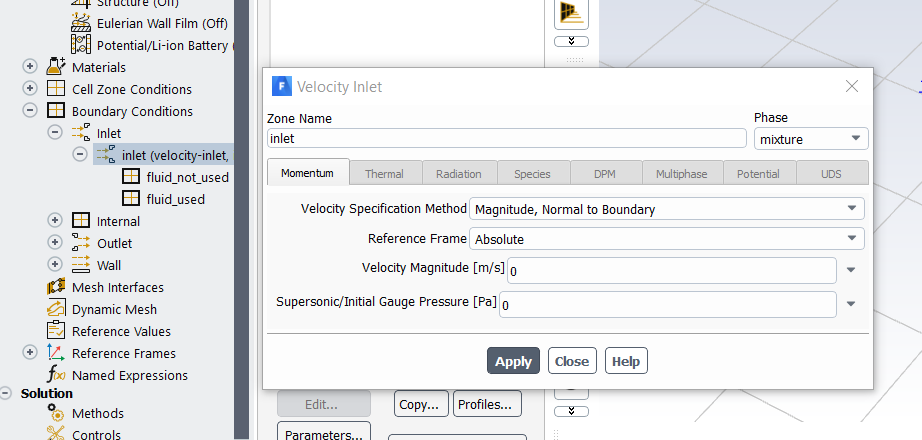 In the following setup, I have used multiphase VOF and defined two phases, (fluid used and the fluid not used so that I can make the fluid used's volume fraction 1). Here there is a velocity defined and when I keep it 0, there is no movement of particles. There is a second velocity setup in dpm.
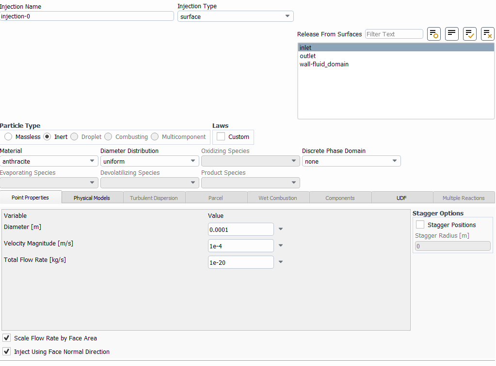 Here, I assumed that the picture earlier was the velocity of the fluid which I set as 0 and the second velocity is that of the particles which i set as 1e-4.
But the particles are not moving in the simulation (all stationary at inlet). How do I rectify this issue?
October 13, 2021 at 6:42 amaitor.amatriain
SubscriberWhy VOF? DPM does exactly what you want.
October 13, 2021 at 6:50 amSumit_Kumar
SubscriberHi aitor?
I actually wanted to know about that. The physics made sense to me in vof. But if there is some gap in my understanding, do let me know
October 13, 2021 at 6:56 amaitor.amatriain
SubscriberWhy do you think that VOF is suitable for your problem?
October 13, 2021 at 8:47 amAmine Ben Hadj Ali
Ansys EmployeeReasons?
October 13, 2021 at 9:34 amSumit_Kumar
SubscriberAlso, I tried the simulation that way. I used laminar setup in viscous. I defined a fluid in the materials, saw in the cell zone boundary conditions that verified that the fluid was mentioned. Then I initialised it. (continuity 0 ).
Next, I entered dpm, used surface in injections and enabled "Scale flow rate by face area" and "Inject using face normal direction" and gave the velocity.
First of all. I could see a different table in computation like:
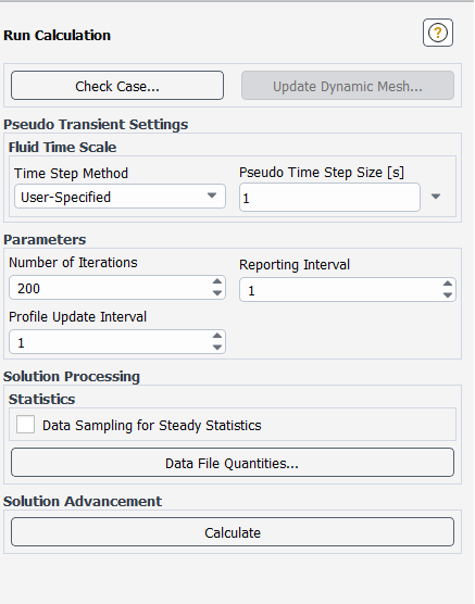 And I calculated it. But it did not solve it. Do let me know if there is some error.
October 13, 2021 at 9:58 amAmine Ben Hadj Ali
Ansys Employee?? Can you please make a stop and describe the current state and what you are now trying to achieve.
October 13, 2021 at 10:11 amSumit_Kumar
SubscriberDrAmine My main goal is to observe the velocity contours made by particles moving in a fluid. Sometimes, when the fluid has enough velocity, the particle loses its velocity and moves with the fluid. Hence, I am trying to simulate the motion of particles moving in a stationary fluid or a fluid moving with a really low velocity so as to observe the profiles that the particles make when I give them different velocities. Experimentally, the particles can move by processes such as electro/magnetophoresis. Hence, I wanted to observe the profiles.
Hope you understand my thought process
October 13, 2021 at 11:10 amAmine Ben Hadj Ali
Ansys EmployeeUnderstood: and now why are using VOF if you want to capture the particle trajectories? Do you have two immiscible fluids on top of the particles?
October 13, 2021 at 11:27 amSumit_Kumar
SubscriberNo, actually I wasn't able to achieve any trajectory while working with dpm only. Hence, i thought that if i used vof, then I could easily keep the volume fraction of a fluid as 1 and have that fluid cover the entire domain. But what I observed was that the trajectories were just that of the fluid.
Would you have an idea on how I model the setup I mentioned earlier
October 13, 2021 at 12:55 pmaitor.amatriain
SubscriberVOF with constant volume fraction along the domain is a single-phase flow. Could you please show us some screenshots of the mesh, boundary conditions, material properties, injections and so on? (including a brief explanation)
October 15, 2021 at 2:22 pmAmine Ben Hadj Ali
Ansys EmployeeDo not make the problem more complex as it actually requires. Just use single phase and try to assess DPM.
October 18, 2021 at 6:24 amSumit_Kumar
SubscriberHi Amine I will tell the procedure I used.
Meshed and defined in/out.
In fluent, first I defined a fluid in materials, set cell zone boundary conditions with that fluid and then just applied dpm, but I couldn't get the option to record particle tracks.
So what I did was after putting the fluid in cell zone bcs, I initialized it from all zones. Then I similarly did a dpm analysis.
But the problem is that it doesnt seem to recogonize that the fluid is there, I know that because the continuity is always zero in my final initialization.
Also another statement while simulating is as follows:
Reversed flow on 27 faces (51.6% area) of pressure-outlet 7.
Like what does that mean. I did not put any boundary conditions on the fluid
October 18, 2021 at 9:24 amAmine Ben Hadj Ali
Ansys EmployeeWhat do you mean with "record particle tracks"? Which post-processing step do you require?
Reversal flow is something else: let's focus first on the point with zero continuity: do you have inlets? If yes: screenshot. Aslo add screenshot of cell zone panel + screenshot of mesh quality check
October 18, 2021 at 11:49 amSumit_Kumar
SubscriberIn the setup phase, if you go to the results section, you can see particle tracks as an option next to mesh, pathlines and contours. So I clicked that and in the release from injections subsection in the table, I selected my injection. Something like this:
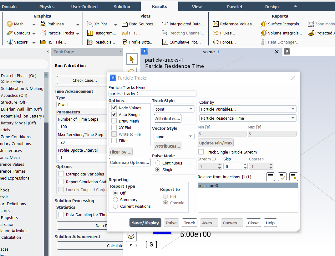 After that, you can create a scene to analyse the flow of particles while the simulation is running so that you know if the particles are not moving
October 19, 2021 at 11:27 amAmine Ben Hadj Ali
Ansys EmployeeOkay: You need rather to export the pictures of the particle tracks objects and combine them into animation either in Fluent or elsewhere (Better to use HSF Format for flexibility and then loading the *cxa file into Fluent to create pictures or animation).
What is now the issue with "zero" continuity? Can you add screenshot of flux report /mass flow rate?
October 19, 2021 at 4:10 pmSumit_Kumar
Subscriber"You need rather to export the pictures of the particle tracks objects and combine them into animation either in Fluent or elsewhere",
I assume you are saying this for after the simulation completes. What I am doing is a process I learnt where I can observe the simulation at each timestep like a scene during the simulation.
The continuity problem is coming after initializing the dpm process after defining the injections and the whole dpm process. Ill attach a screenshot below the text. But the problem it states that the pressure information is not given at the boundaries, hence a constant pressure has been taken.
The point is, the particles are not driven by pressure, they are driven by an external force applied. Hence, it doesnt make sense to specifically have a pressure boundary condition
October 19, 2021 at 4:13 pmRob
Forum ModeratorYou're applying an external body force to the particles and not modelling (much) fluid motion? Unless you're modelling the particles as transient I'm not sure you'll get what you're expecting from the model.
October 19, 2021 at 4:20 pmSumit_Kumar
SubscriberThe model is so that the fluid is stationary initially or moving with a minimal velocity, basically I have just assumed the fluid to be prefilled as an initialization (cell zone boundary conditions (fluid) + initialization from all zones (zero velocity)). After this, I just performed dpm.
"You're applying an external body force to the particles and not modelling (much) fluid motion?", yes, this is somewhat inspired from processes like dielectrophoresis just to observe the net force (opposed by drag).
"Unless you're modelling the particles as transient I'm not sure you'll get what you're expecting from the model."
I am not sure as to how I should specifically model the particles as transient, but the general model has been taken as transient by me.
October 20, 2021 at 6:04 amAmine Ben Hadj Ali
Ansys EmployeeThe pressure information message is related to initialization. Do not worry much about it and start running.
October 20, 2021 at 10:14 amRob
Forum ModeratorIf the whole model is transient that's fine.
October 20, 2021 at 2:58 pmSumit_Kumar
SubscriberYes, I was also convinced that the physics was accurate. But the particles injected do not seem to move during the simulation.
Also, I am unable to understand the why the reverse flow message was coming earlier while computing the solution. I feel that this is restricting particle movement.
October 20, 2021 at 3:00 pmRob
Forum ModeratorMaybe they don't. How big is the time step, how long did you run the model and are the forces enough to counteract any fluid movement?
October 31, 2021 at 11:22 amSumit_Kumar
SubscriberSee thats just it. The time step size is not changing the result as if it did, I would have seen atleast an infinitesimal movement. But the flow is reversed. I even tried to modify the boundary conditions for the fluid making a pressure inlet and a pressure outlet and setting the gauge pressures to 0 for the initialisation before performing DPM. But this does not change anything.
Till now, I do not understand what exactly went wrong with the physics, as it seems pretty accurate in my eyes
November 1, 2021 at 2:20 pmRob
Forum ModeratorHow fast is the injection, how fast and what material is it injected into? What is the particle size?
November 1, 2021 at 2:53 pmSumit_Kumar
SubscriberAs of now, the inlet dimensions are 0.6mm*0.04mm, the particle size is 0.1 um. The particle I am currrently using as a test is anthracite and on water as a stationary fluid. The velocity assigned to the particles is 1e-5m/s.
These parameters are fine, but it would atleast show if the particles are moving by the virtue of their velocity itself. Just to clarify if I am wrong
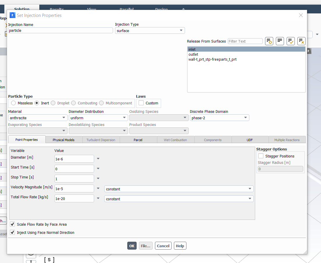 This is the velocity I am assigning. I hope this only shows the velocity of the particle. The boundary conditions for the fluid have been set as pressure inlet and pressure outlet and the gauge pressures are initialised as 0 so as to maintain the stationary fluid thing going on.
November 1, 2021 at 2:54 pmSumit_Kumar
SubscriberI also went to multiphase and changed the model to eulerian(inhomogenous) with one discrete phase, but still couldn't get a result
November 1, 2021 at 5:16 pmRob
Forum ModeratorCalculate the momentum of the injection. Then calculate the Stokes relaxation time and terminal velocity.
At 0.1 micron and 0.01mm/s the particle isn't going to go anywhere other than by Brownian motion, diffusion or numerical errors: ie you won't see it move unless the fluid is also moving.
November 1, 2021 at 5:43 pmSumit_Kumar
Subscriber"At 0.1 micron and 0.01mm/s the particle isn't going to go anywhere other than by Brownian motion, diffusion or numerical errors: ie you won't see it move unless the fluid is also moving.", this does make sense.
But how do I calculate the momentum of injection and the relaxation time?
November 2, 2021 at 11:48 amRob
Forum ModeratorI tend to use Excel as I can't find my calculator and don't like the Win10 one. As to what I'm calculating, a basic text book on particles will give you the equations (I use Coulson & Richardson's Chemical Engineering books as they're on my desk) or Wiki probably has the information.
Viewing 41 reply threads- The topic ‘Regarding pre filling a geometry before multiphase vof simulation’ is closed to new replies.
Innovation SpaceTrending discussionsTop Contributors-
4763
-
1565
-
1386
-
1242
-
1021
Top Rated Tags© 2026 Copyright ANSYS, Inc. All rights reserved.
Ansys does not support the usage of unauthorized Ansys software. Please visit www.ansys.com to obtain an official distribution.
-


Ansys Assistant

Welcome to Ansys Assistant!
An AI-based virtual assistant for active Ansys Academic Customers. Please login using your university issued email address.
Hey there, you are quite inquisitive! You have hit your hourly question limit. Please retry after '10' minutes. For questions, please reach out to ansyslearn@ansys.com.
RETRY


