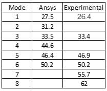
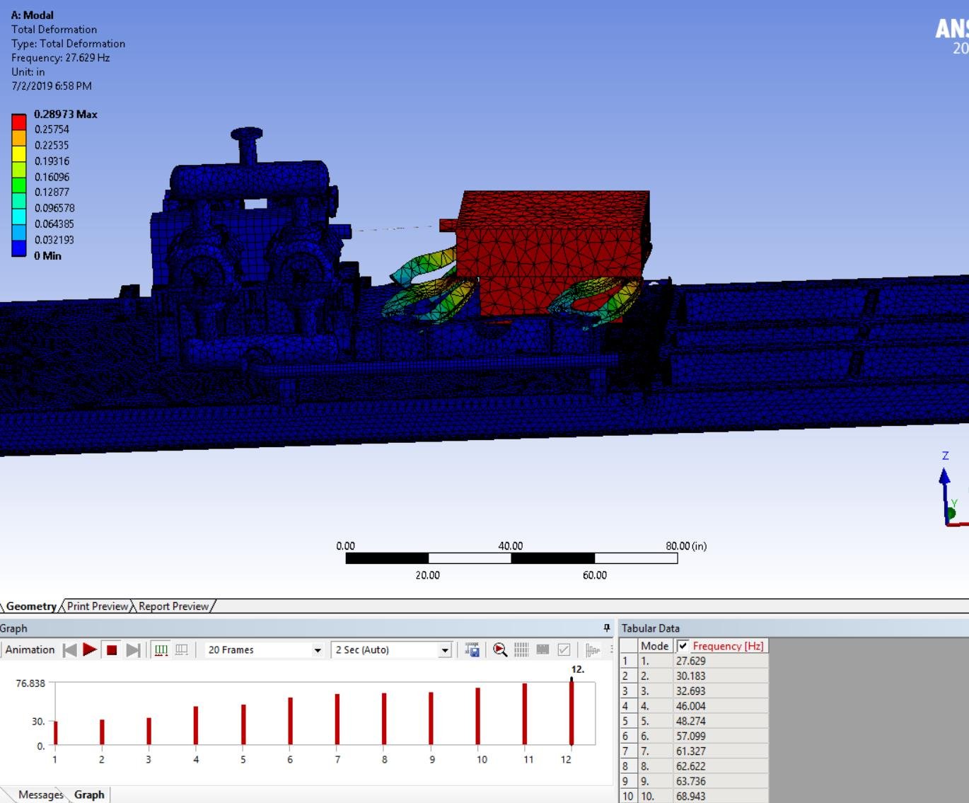
I am trying to extract 6 mode shapes. The values are as follows in Hz from Modal Analysis:
27.5, 31.2, 33.5, 44.6, 46.4, 50.2.
I am just trying to match the results with the report I have from some outsourced company. According to them for same model I should get results as:
26.4, 33.4, 46.9, 50.2, 55.7 and 62.
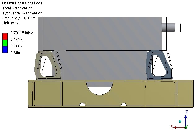
So according to me I am getting extra modes in-between. I have used I beam connection for holes with dia of 0.5. For fixtures I have used elastic support to the base plate because that will be filled with concrete. The value for elastic support I have used is of 10000.
To describe my setup: Engine, compressor frame and cylinders are mounted on pedestal. Entire pedestal is mounted on plate called deck plate. Deck plate is welded to frame made up of I beams.
So is there anyway that you can guide me to rectify my mistake, so that can get desired results.