-
-
October 31, 2021 at 8:04 am
vsjay3
SubscriberHi everyone,
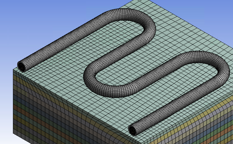
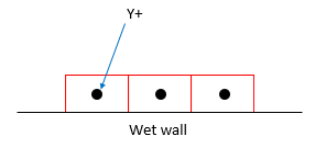
This is a simple question but I'm not quite sure what to do about it. I have water flowing inside a 4-pass pipe which is buried in sand. The sand is heated and the water will absorb the heat through the pipe wall. But since the problem involves heat transfer, it is important that I pay special attention to the fluid-pipe wall interface. To maintain a y+ = 1, my calculated first layer height for inflation cell is 0.014 mm. I included 20 inflation layers and the pipe inside diameter is 15mm. I used the Sweep method to mesh the coolant. The orthogonal quality and skewness seem to be quite good. But since the inflation layers are quite thin (because the cell height is low), I get quite bad aspect ratio result. Below are the results:
November 1, 2021 at 12:49 pmKarthik Remella
AdministratorHello In my opinion, this is a fair mesh. When you use a Y+ ~ 1 mesh, the aspect ratio of the elements in the BL is going to be high. In your case, did you plot the Wall Distance contours to double-check if you are seeing any anomaly?
Karthik
November 1, 2021 at 1:03 pmvsjay3
Subscriber
Thank you very much for your response. Appreciate it.
(I hope it works because I cannot reduce the length of inflation cells (parallel to wall) since that will increase the total number of elements and I am using the student version of Ansys Fluent).
As for your question - I have not run the simulation yet. To plot the wall distance contours, I have to first run the complete simulation right? Or is there a way to check that before running the simulation?
Also, since I am new to Fluent, may I know what the anomaly will look like (as an example) when I do plot the contours?
Thank you very much!
November 1, 2021 at 1:07 pmKarthik Remella
AdministratorYou don't need to solve the model. You can initialize the model and plot this wall distance. You should see the correct first layer thickness you specified for meshing the model (within reason). If you see really high or low values, then you are looking at some erroneous results.
Karthik
November 1, 2021 at 4:43 pmvsjay3
Subscriber
I will proceed to plot the wall y+ contours and check. However, since I am quite new to Fluent please bear with me on this question:
When I plot the wall y+ in Fluent, does the fluent calculate the y+ for only the first layer of cells adjacent to the wall?
Thank you very much!
November 1, 2021 at 5:02 pmRob
Forum ModeratorIf you pick the "wet" wall, turn off node values and turn off global range you'll just see the values for that surface.
November 1, 2021 at 5:20 pmNovember 1, 2021 at 5:29 pmKarthik Remella
AdministratorYes! Your understanding is correct. Try plotting the parameter "Cell Wall Distance'. It is the distribution of the normal distance of each cell centroid from the wall boundaries. Two times this value is your first layer thickness.
November 3, 2021 at 12:57 pmvsjay3
SubscriberHi, thanks for the advice. I will proceed to do so. However, I do have a side question I need to ask. I feel that it's better I ask in this thread since it's the same model. In Ansys Meshing program, my mesh orthogonal quality has the following statistics:
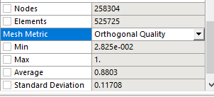 As you can see the minimum is above 0.01. But when I check mesh in Ansys Fluent, it gives me the below message. Now which program is lying? :)

Thank you for your advice in advance!
November 3, 2021 at 2:44 pmRob
Forum ModeratorNeither. Fluent uses a slightly different calculation method which only tends to be obvious when the cells are highly skewed. However, unless you're creating poly cells I'd look at "skew" in Workbench Meshing rather than ortho quality.
November 3, 2021 at 2:50 pmvsjay3
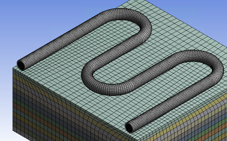
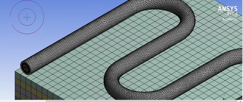
SubscriberThanks for answering. Also, when I ran my simulation for the below model (first image) where the pipe wall (grey color) was meshed in hexahedral cells, the energy residual diverged (i.e., rose up midway and became constant). Later when I re-meshed the pipe wall (of the same model) using tetrahedral cells (second image), the energy residual converged. Do you happen to have any idea why that would happen?
November 3, 2021 at 2:59 pmRob
Forum ModeratorCheck the resolution and skew. Chances are the tet mesh is better quality. How does the block surrounding the pipe look?
November 3, 2021 at 3:59 pmvsjay3
Subscriber
Thank you for replying. Actually the mesh of the sand block (green color block) surrounding the pipe in both instances (when pipe wall was meshed with hex cells and later when pipe wall was re-meshed with tet mesh) was meshed with tetrahedral cells. Maybe because the second time both sand and pipe wall were meshed with tet cells, maybe they synced better?
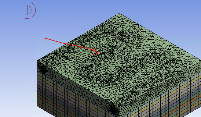
Skewness there's not much of a difference between the hex and tet mesh (in fact hex mesh gave slightly better skewness results obviously cuz its structured). Also, what did you mean when you said resolution? I cannot find that in the mesh metric list to check for statistics.
November 3, 2021 at 4:00 pmvsjay3
SubscriberHi thanks for replying. Appreciate it. Actually in both instances (when the pipe wall was meshed with hex cells and later re-meshed with tet cells) the sand block (green color block) covering the pipe wall was meshed with tet cells. So , maybe the sand block and pipe wall synced better when both were meshed with tet cells after re-meshing?
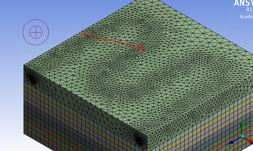
The skewness was slightly better for hex mesh (obviously since its structured) compared to tet mesh. But what do you mean by resolution? I do not see it in the mesh metric list under statistics.
November 3, 2021 at 4:36 pmRob
Forum ModeratorI think part of the problem is jump in cell size in the solids. Look at the shape of the tet cells in the top layer between the pipe and neighbouring zone (green-ish block).
Resolution isn't easy to measure - it's checked by looking and understanding so takes a bit of practice. Basically, it's whether you have enough cells to capture the flow/thermal/whatever gradients.
November 3, 2021 at 5:01 pmvsjay3
Subscriber
Thanks again. I understand that there is a significant jump of cell size from pipe wall to the green block. But this jump was the same in both cases where the pipe wall was meshed with hex cells and tet cells. So it's quite hard to understand how the pipe-wall mesh transferring from hex to a tet mesh led to better performance. I honestly expected the model to perform better when the pipe wall was meshed with hex cells since it's more structured compared to tet cells.
November 3, 2021 at 5:13 pmRob
Forum ModeratorIt depends on what was causing the problems. Tets tend to be more forgiving if squashed a bit.
November 3, 2021 at 5:21 pmvsjay3
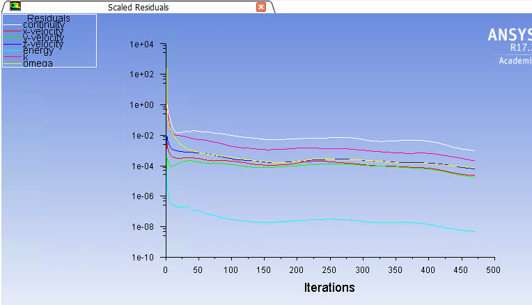
SubscriberI understand thanks. After the re-meshing of pipe wall with the tet mesh, the solution converged. However, the continuity residual did not reach 0.001. So I don't know why Ansys Fluent indicated that the solution completed. Because even my 500 iteration mark was not reached. I thought in order for the solution to be marked as completed, either all residuals have to reach their convergence value or the iteration number has to be reached. In this case, neither occurred but solution completed. Does the below residual plot of continuity seem reasonable to you?
November 4, 2021 at 11:16 amKarthik Remella
AdministratorHello Let me put it this way - the residual trend I'm seeing is not bad. Do check the overall heat & mass balances using the Flux Reports in Fluent.
Regarding the convergence criteria, double-check the residual values printed to the console. The plots can be misleading because of the log scale on the y-axis.
Karthik
November 4, 2021 at 12:01 pmvsjay3
Subscriber
Thank you very much for replying. I actually created a report definition for mass-weighted average temperature at the outlet and monitored the outlet temperature, and it stayed constant over iterations. (However, I was not able to set convergence criteria for the report definition because I cannot find that option in Fluent under Solution tab). But I guess since the outlet temperature stayed constant the solution is fine?
Anyways, I also checked the flux report for mass flowrate by selecting inlet and outlet and seeing if net flux imbalance was less than 1% of the smallest flux (between mass flowrates of inlet or outlet) and it was very small (like 2e-16). Is the way I checked the fluxes correct? (this is my first time checking fluxes)
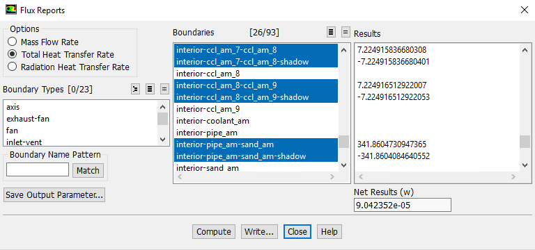
Also, how do I check for the total heat transfer flux? I do not know what boundaries to select.
Any advice would be appreciated!
Thank you!
November 4, 2021 at 12:09 pmKarthik Remella
AdministratorYep, your thoughts on the flux balance are correct.
Regarding heat imbalance, think of all the boundaries where you will potentially have heat transfer. If you have volumetric sources, Fluent will automatically calculate the net heating from these (in the newer versions). The net heat imbalance should be less than 1 % of the smallest heat flux crossing the boundary (within reason - you will need to be practical here).
Karthik
November 4, 2021 at 2:40 pmvsjay3
Subscriber
Regarding the flux for total heat transfer rate:
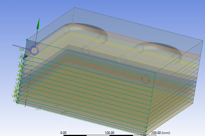
My model has several soil layers on top of each other and a cooling pipe buried in the very top layer (shown below). Therefore, if I select (a) all wall-interfaces between the soil layers, (b) the wall interface between pipe wall and its surrounding soil layer, and (c) wall interface between coolant and pipe wall, then calculate the net flux for all of them at once and check if the final net flux is lower than 1% of the smallest flux, is that correct?
Thank you!
Viewing 21 reply threads- The topic ‘Re: High aspect ratio’ is closed to new replies.
Innovation SpaceTrending discussionsTop Contributors-
4763
-
1565
-
1386
-
1242
-
1021
Top Rated Tags© 2026 Copyright ANSYS, Inc. All rights reserved.
Ansys does not support the usage of unauthorized Ansys software. Please visit www.ansys.com to obtain an official distribution.
-


Ansys Assistant

Welcome to Ansys Assistant!
An AI-based virtual assistant for active Ansys Academic Customers. Please login using your university issued email address.
Hey there, you are quite inquisitive! You have hit your hourly question limit. Please retry after '10' minutes. For questions, please reach out to ansyslearn@ansys.com.
RETRY
