
TAGGED: #thermal-radiation, radiation
-
-
December 9, 2024 at 12:49 pm
thomas.fellinger
SubscriberHello,
I get an unknow error doing a thermal simulation by radiation:
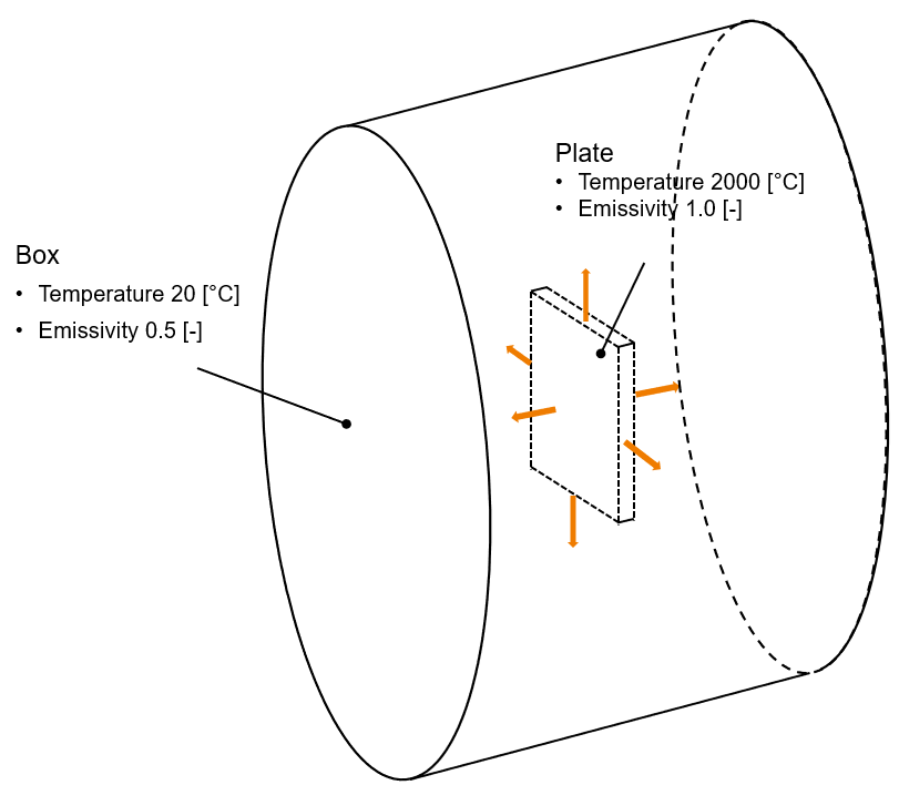
A plate with a certain temperature is surrounded by a box. I want to simulate to investigate the temperature over time.
If the box has a mesh size of 20mm and the plate 5mm than it works. Changing the mesh size only of the plate to 1mm, an unknow error occurs, see both solver output files below.
I also tried to reduce the mesh size of the box - no positive result.Someone my have an idea why this happens (solver setting, boundares, mesh,...)?
Case 1: Error 1mm mesh size of the plate, other bodies 20mm

Solver Output
Ansys Mechanical Enterprise Academic Research
*------------------------------------------------------------------*
| |
| W E L C O M E T O T H E A N S Y S (R) P R O G R A M |
| |
*------------------------------------------------------------------*
***************************************************************
* ANSYS MAPDL 2022 R2 LEGAL NOTICES *
***************************************************************
* *
* Copyright 1971-2022 Ansys, Inc. All rights reserved. *
* Unauthorized use, distribution or duplication is *
* prohibited. *
* *
* Ansys is a registered trademark of Ansys, Inc. or its *
* subsidiaries in the United States or other countries. *
* See the Ansys, Inc. online documentation or the Ansys, Inc. *
* documentation CD or online help for the complete Legal *
* Notice. *
* *
***************************************************************
* *
* THIS ANSYS SOFTWARE PRODUCT AND PROGRAM DOCUMENTATION *
* INCLUDE TRADE SECRETS AND CONFIDENTIAL AND PROPRIETARY *
* PRODUCTS OF ANSYS, INC., ITS SUBSIDIARIES, OR LICENSORS. *
* The software products and documentation are furnished by *
* Ansys, Inc. or its subsidiaries under a software license *
* agreement that contains provisions concerning *
* non-disclosure, copying, length and nature of use, *
* compliance with exporting laws, warranties, disclaimers, *
* limitations of liability, and remedies, and other *
* provisions. The software products and documentation may be *
* used, disclosed, transferred, or copied only in accordance *
* with the terms and conditions of that software license *
* agreement. *
* *
* Ansys, Inc. is a UL registered *
* ISO 9001:2015 company. *
* *
***************************************************************
* *
* This product is subject to U.S. laws governing export and *
* re-export. *
* *
* For U.S. Government users, except as specifically granted *
* by the Ansys, Inc. software license agreement, the use, *
* duplication, or disclosure by the United States Government *
* is subject to restrictions stated in the Ansys, Inc. *
* software license agreement and FAR 12.212 (for non-DOD *
* licenses). *
* *
***************************************************************
2022 R2
Point Releases and Patches installed:
ANSYS, Inc. License Manager 2022 R2
Discovery 2022 R2
SpaceClaim 2022 R2
Ansys Sherlock 2022 R2
Autodyn 2022 R2
LS-DYNA 2022 R2
CFD-Post only 2022 R2
CFX (includes CFD-Post) 2022 R2
Chemkin 2022 R2
FENSAP-ICE 2022 R2
Fluent (includes CFD-Post) 2022 R2
Polyflow (includes CFD-Post) 2022 R2
Forte (includes EnSight) 2022 R2
TurboGrid 2022 R2
ICEM CFD 2022 R2
Aqwa 2022 R2
Speos 2022 R2
Speos HPC 2022 R2
optiSLang 2022 R2
Additive 2022 R2
Customization Files for User Programmable Features 2022 R2
Mechanical Products 2022 R2
Remote Solve Manager Standalone Services 2022 R2
Ansys Sound - SAS 2022 R2
Viewer 2022 R2
ACIS Geometry Interface 2022 R2
AutoCAD Geometry Interface 2022 R2
Catia, Version 4 Geometry Interface 2022 R2
Catia, Version 5 Geometry Interface 2022 R2
Catia, Version 6 Geometry Interface 2022 R2
Creo Elements/Direct Modeling Geometry Interface 2022 R2
Creo Parametric Geometry Interface 2022 R2
Inventor Geometry Interface 2022 R2
JTOpen Geometry Interface 2022 R2
NX Geometry Interface 2022 R2
Parasolid Geometry Interface 2022 R2
Solid Edge Geometry Interface 2022 R2
SOLIDWORKS Geometry Interface 2022 R2
***** MAPDL COMMAND LINE ARGUMENTS *****
BATCH MODE REQUESTED (-b) = NOLIST
INPUT FILE COPY MODE (-c) = COPY
DISTRIBUTED MEMORY PARALLEL REQUESTED
15 PARALLEL PROCESSES REQUESTED WITH SINGLE THREAD PER PROCESS (FORCED)
TOTAL OF 15 CORES REQUESTED
INPUT FILE NAME = E:\Test_Beam_1.63MW_Sig5mm\_ProjectScratch\ScrA868\dummy.dat
OUTPUT FILE NAME = E:\Test_Beam_1.63MW_Sig5mm\_ProjectScratch\ScrA868\solve.out
START-UP FILE MODE = NOREAD
STOP FILE MODE = NOREAD
GPU ACCELERATOR OPTION REQUESTED
1 GPU ACCELERATOR DEVICES REQUESTED
RELEASE= 2022 R2 BUILD= 22.2 UP20220516 VERSION=WINDOWS x64
CURRENT JOBNAME=file0 13:36:36 DEC 07, 2024 CP= 0.219
PARAMETER _DS_PROGRESS = 999.0000000
/INPUT FILE= ds.dat LINE= 0
*** NOTE *** CP = 3.438 TIME= 13:36:41
The /CONFIG,NOELDB command is not valid in a distributed memory
parallel solution. Command is ignored.
*GET _WALLSTRT FROM ACTI ITEM=TIME WALL VALUE= 13.6113889
TITLE=
Test_Radiation--Transient Thermal (B5)
ACT Extensions:
LSDYNA, 2022.2
5f463412-bd3e-484b-87e7-cbc0a665e474, wbex
/COM, ANSYSMotion, 2022.2
20180725-3f81-49eb-9f31-41364844c769, wbex
SET PARAMETER DIMENSIONS ON _WB_PROJECTSCRATCH_DIR
TYPE=STRI DIMENSIONS= 248 1 1
PARAMETER _WB_PROJECTSCRATCH_DIR(1) = E:\Test_Beam_1.63MW_Sig5mm\_ProjectScratch\ScrA868\
SET PARAMETER DIMENSIONS ON _WB_SOLVERFILES_DIR
TYPE=STRI DIMENSIONS= 248 1 1
PARAMETER _WB_SOLVERFILES_DIR(1) = E:\Test_Beam_1.63MW_Sig5mm\Test_Radiation_files\dp0\SYS-30\MECH\
SET PARAMETER DIMENSIONS ON _WB_USERFILES_DIR
TYPE=STRI DIMENSIONS= 248 1 1
PARAMETER _WB_USERFILES_DIR(1) = E:\Test_Beam_1.63MW_Sig5mm\Test_Radiation_files\user_files\
--- Data in consistent NMM units. See Solving Units in the help system for more
MPA UNITS SPECIFIED FOR INTERNAL
LENGTH = MILLIMETERS (mm)
MASS = TONNE (Mg)
TIME = SECONDS (sec)
TEMPERATURE = CELSIUS (C)
TOFFSET = 273.0
FORCE = NEWTON (N)
HEAT = MILLIJOULES (mJ)
INPUT UNITS ARE ALSO SET TO MPA
*** MAPDL - ENGINEERING ANALYSIS SYSTEM RELEASE 2022 R2 22.2 ***
Ansys Mechanical Enterprise Academic Research
00000000 VERSION=WINDOWS x64 13:36:41 DEC 07, 2024 CP= 3.438
Test_Radiation--Transient Thermal (B5)
***** MAPDL ANALYSIS DEFINITION (PREP7) *****
*********** Nodes for the whole assembly ***********
*********** Elements for Body 1 "cover1" ***********
*********** Elements for Body 2 "cover2" ***********
*********** Elements for Body 3 "cover3" ***********
*********** Elements for Body 4 "cover4" ***********
*********** Elements for Body 5 "End1" ***********
*********** Elements for Body 6 "End2" ***********
*********** Elements for Body 7 "SYS-29\400x400x5\Solid" ***********
*********** Send User Defined Coordinate System(s) ***********
*********** Send Materials ***********
*********** Create Contact "Contact Region" ***********
Real Constant Set For Above Contact Is 9 & 8
*********** Create Contact "Contact Region 2" ***********
Real Constant Set For Above Contact Is 11 & 10
*********** Create Contact "Contact Region 3" ***********
Real Constant Set For Above Contact Is 13 & 12
*********** Create Contact "Contact Region 4" ***********
Real Constant Set For Above Contact Is 15 & 14
*********** Send Named Selection as Node Component ***********
*********** Send Named Selection as Node Component ***********
*********** Send Named Selection as Node Component ***********
*********** Send Named Selection as Element Component ***********
*********** Send Named Selection as Node Component ***********
*********** Send Named Selection as Node Component ***********
*********** Send Named Selection as Node Component ***********
*********** Define Temperature Constraint ***********
*********** Define Temperature Constraint ***********
*********** Create "ToSurface(Closed)" Radiation ***********
*********** Create "ToSurface(Closed)" Radiation ***********
***************** Define Uniform Initial temperature ***************
***** ROUTINE COMPLETED ***** CP = 33.188
--- Number of total nodes = 3895043
--- Number of contact elements = 960
--- Number of spring elements = 0
--- Number of bearing elements = 0
--- Number of solid elements = 828438
--- Number of condensed parts = 0
--- Number of total elements = 829398
*GET _WALLBSOL FROM ACTI ITEM=TIME WALL VALUE= 13.6130556
****************************************************************************
************************* SOLUTION ********************************
****************************************************************************
***** MAPDL SOLUTION ROUTINE *****
PERFORM A TRANSIENT ANALYSIS
THIS WILL BE A NEW ANALYSIS
STEP BOUNDARY CONDITION KEY= 1
USE PRECONDITIONED CONJUGATE GRADIENT SOLVER
CONVERGENCE TOLERANCE = 1.00000E-08
MAXIMUM ITERATION = NumNode*DofPerNode* 1.0000
CONTACT INFORMATION PRINTOUT LEVEL 1
DO NOT SAVE ANY RESTART FILES AT ALL
DO NOT COMBINE ELEMENT MATRIX FILES (.emat) AFTER DISTRIBUTED PARALLEL SOLUTION
DO NOT COMBINE ELEMENT SAVE DATA FILES (.esav) AFTER DISTRIBUTED PARALLEL SOLUTION
Use Full Nonlinear Thermal Transient Solution
NLHIST: ADDED NODAL RESULTS HISTORY FOR:
NAME = MAX_TEMP
ITEM/COMP = TEMPMAX
NODE = 0
NLHIST: ADDED NODAL RESULTS HISTORY FOR:
NAME = MIN_TEMP
ITEM/COMP = TEMPMIN
NODE = 0
********* Initial Time Increment Check And Fourier Modulus *********
Specified Initial Time Increment: 0.05
Estimated Increment Needed, le*le/alpha, Body 1: 13.957
Estimated Increment Needed, le*le/alpha, Body 2: 13.957
Estimated Increment Needed, le*le/alpha, Body 3: 13.957
Estimated Increment Needed, le*le/alpha, Body 4: 13.957
Estimated Increment Needed, le*le/alpha, Body 5: 9.39451
Estimated Increment Needed, le*le/alpha, Body 6: 9.39453
Estimated Increment Needed, le*le/alpha, Body 7: 0.0563124
****************************************************
******************* SOLVE FOR LS 1 OF 1 ****************
SPECIFIED CONSTRAINT TEMP FOR PICKED NODES
SET ACCORDING TO TABLE PARAMETER = _LOADVARI939
Memory resident data base increased from 2048 MB to 4096 MB.
SPECIFIED CONSTRAINT TEMP FOR PICKED NODES
REAL= 20.0000000 IMAG= 0.00000000
SELECT COMPONENT _CM617
SELECT ALL ELEMENTS HAVING ANY NODE IN NODAL SET.
324788 ELEMENTS (OF 829398 DEFINED) SELECTED FROM
984002 SELECTED NODES BY ESLN COMMAND.
GENERATE SURFACE LOAD RDSF ON SURFACE DEFINED BY ALL SELECTED NODES
EMISSIVITY = 1.00 ENCLOSURE NUMBER = 1.
NUMBER OF RDSF ELEMENT FACE LOADS STORED = 328000
ALL SELECT FOR ITEM=NODE COMPONENT=
IN RANGE 1 TO 3895043 STEP 1
3895043 NODES (OF 3895043 DEFINED) SELECTED BY NSEL COMMAND.
ENCLOSURE= 1 VIEWFACTOR SCALE METHOD = 1
ITERATIONS = 100
TOLERANCE = 1.000000047E-03
SELECT COMPONENT _CM676
SELECT ALL ELEMENTS HAVING ANY NODE IN NODAL SET.
29398 ELEMENTS (OF 829398 DEFINED) SELECTED FROM
84844 SELECTED NODES BY ESLN COMMAND.
GENERATE SURFACE LOAD RDSF ON SURFACE DEFINED BY ALL SELECTED NODES
EMISSIVITY = 0.500 ENCLOSURE NUMBER = 1.
NUMBER OF RDSF ELEMENT FACE LOADS STORED = 27966
ALL SELECT FOR ITEM=NODE COMPONENT=
IN RANGE 1 TO 3895043 STEP 1
3895043 NODES (OF 3895043 DEFINED) SELECTED BY NSEL COMMAND.
ALL SELECT FOR ITEM=NODE COMPONENT=
IN RANGE 1 TO 3895043 STEP 1
3895043 NODES (OF 3895043 DEFINED) SELECTED BY NSEL COMMAND.
ALL SELECT FOR ITEM=ELEM COMPONENT=
IN RANGE 1 TO 1215626 STEP 1
829398 ELEMENTS (OF 829398 DEFINED) SELECTED BY ESEL COMMAND.
PRINTOUT RESUMED BY /GOP
DO NOT USE AUTOMATIC TIME STEPPING THIS LOAD STEP
USE 2 SUBSTEPS INITIALLY THIS LOAD STEP FOR ALL DEGREES OF FREEDOM
FOR AUTOMATIC TIME STEPPING:
USE 2 SUBSTEPS AS A MAXIMUM
USE 2 SUBSTEPS AS A MINIMUM
TIME= 0.10000
INCLUDE TRANSIENT EFFECTS FOR ALL DEGREES OF FREEDOM THIS LOAD STEP
ERASE THE CURRENT DATABASE OUTPUT CONTROL TABLE.
WRITE ALL ITEMS TO THE DATABASE WITH A FREQUENCY OF NONE
FOR ALL APPLICABLE ENTITIES
WRITE NSOL ITEMS TO THE DATABASE WITH A FREQUENCY OF ALL
FOR ALL APPLICABLE ENTITIES
WRITE RSOL ITEMS TO THE DATABASE WITH A FREQUENCY OF ALL
FOR ALL APPLICABLE ENTITIES
WRITE EANG ITEMS TO THE DATABASE WITH A FREQUENCY OF ALL
FOR ALL APPLICABLE ENTITIES
WRITE VENG ITEMS TO THE DATABASE WITH A FREQUENCY OF ALL
FOR ALL APPLICABLE ENTITIES
WRITE FFLU ITEMS TO THE DATABASE WITH A FREQUENCY OF ALL
FOR ALL APPLICABLE ENTITIES
WRITE CONT ITEMS TO THE DATABASE WITH A FREQUENCY OF ALL
FOR ALL APPLICABLE ENTITIES
WRITE MISC ITEMS TO THE DATABASE WITH A FREQUENCY OF ALL
FOR ALL APPLICABLE ENTITIES
CONVERGENCE ON HEAT BASED ON THE NORM OF THE N-R LOAD
WITH A TOLERANCE OF 0.1000E-03 AND A MINIMUM REFERENCE VALUE OF 0.1000E-02
USING THE L2 NORM (CHECK THE SRSS VALUE)
UNDER RELAXATION FOR RADIATION FLUX= 0.10000
TOLERENCE FOR RADIOSITY FLUX= 0.00001
USING JACOBI ITERATIVE SOLVER FOR RADIOSITY SOLUTION
FOR 3D ENCLOSURES.
USING GSEIDEL ITERATIVE SOLVER FOR RADIOSITY SOLUTION
FOR 2D ENCLOSURES.
MAXIMUM NUMBER OF ITERATIONS= 1000
TOLERENCE FOR ITERATIVE SOLVER= 0.00010
RELAXATION FOR ITERATIVE SOLVER= 0.10000
HEMICUBE RESOLUTION= 100
MIN NORMALIZED DIST BEFORE AUTO SUBDIVIDE= 1.000000000E-09
SELECT COMPONENT _CM617
SELECT ALL ELEMENTS HAVING ANY NODE IN NODAL SET.
324788 ELEMENTS (OF 829398 DEFINED) SELECTED FROM
984002 SELECTED NODES BY ESLN COMMAND.
BEFORE SYMMETRIZATION:
NUMBER OF RADIATION NODES CREATED = 328002
NUMBER OF RADIOSITY SURFACE ELEMENTS CREATED = 328000
AFTER SYMMETRIZATION:
FULL NUMBER OF RADIATION NODES CREATED = 328002
FULL NUMBER OF RADIOSITY SURFACE ELEMENTS CREATED = 328000
ALL SELECT FOR ITEM=NODE COMPONENT=
IN RANGE 1 TO 4223045 STEP 1
4223045 NODES (OF 4223045 DEFINED) SELECTED BY NSEL COMMAND.
ALL SELECT FOR ITEM=ELEM COMPONENT=
IN RANGE 1 TO 1543626 STEP 1
1157398 ELEMENTS (OF 1157398 DEFINED) SELECTED BY ESEL COMMAND.
SELECT COMPONENT _CM676
SELECT ALL ELEMENTS HAVING ANY NODE IN NODAL SET.
29398 ELEMENTS (OF 1157398 DEFINED) SELECTED FROM
84844 SELECTED NODES BY ESLN COMMAND.
BEFORE SYMMETRIZATION:
NUMBER OF RADIATION NODES CREATED = 28440
NUMBER OF RADIOSITY SURFACE ELEMENTS CREATED = 27966
AFTER SYMMETRIZATION:
FULL NUMBER OF RADIATION NODES CREATED = 28440
FULL NUMBER OF RADIOSITY SURFACE ELEMENTS CREATED = 27966
ALL SELECT FOR ITEM=NODE COMPONENT=
IN RANGE 1 TO 4251485 STEP 1
4251485 NODES (OF 4251485 DEFINED) SELECTED BY NSEL COMMAND.
ALL SELECT FOR ITEM=ELEM COMPONENT=
IN RANGE 1 TO 1571592 STEP 1
1185364 ELEMENTS (OF 1185364 DEFINED) SELECTED BY ESEL COMMAND.
*GET ANSINTER_ FROM ACTI ITEM=INT VALUE= 0.00000000
*IF ANSINTER_ ( = 0.00000 ) NE
0 ( = 0.00000 ) THEN
*ENDIF
*** NOTE *** CP = 67.344 TIME= 13:36:52
The automatic domain decomposition logic has selected the MESH domain
decomposition method with 15 processes per solution.
***** MAPDL SOLVE COMMAND *****
CALCULATING VIEW FACTORS USING HEMICUBE METHOD
RETRIEVED 1 ENCLOSURES.
TOTAL OF 355966 DEFINED ELEMENT FACES.
# ENCLOSURE = 1 # SURFACES =355966 # NODES =356442
******************************************************************************
V I E W F A C T O R S M O O T H I N G
******************************************************************************
Smoothing of viewfactor matrix...
Max iterations = 100
Tolerance = 0.001
row sum total should be = 355966.0000
row sum total before forcing symmetry = 355965.9605
row sum total after forcing symmetry = 355965.9605
row sum total after smoothing = 355966.0025
Raw rowsum error min = -5.0902e-05
Raw rowsum error max = 8.3447e-07
Raw rowsum error mean = -1.1107e-07 +/- 4.1666e-07
Symmetric rowsum error min = -5.0902e-05
Symmetric rowsum error max = 8.3447e-07
Symmetric rowsum error mean = -1.1107e-07 +/- 6.2869e-08
Smoothed rowsum error min = -3.5763e-07
Smoothed rowsum error max = 5.9605e-07
Smoothed rowsum error mean = 6.9275e-09 +/- 1.4241e-09
number of iterations to smooth = 1
******************************************************************************
E N D O F V I E W F A C T O R S M O O T H I N G
******************************************************************************
TIME OF CALCULATION FOR THIS ENCLOSURE = 1659.38
CHECKING VIEW FACTOR SUM
VIEW FACTOR CALCULATION COMPLETE
WRITING VIEW FACTORS TO FILE file0.vf
VIEW FACTORS WERE WRITTEN TO FILE file0.vf
*** WARNING *** CP = 2502.359 TIME= 15:15:12
Some radiation enclosures have viewfactor scaling. Use VFSM,STAT
command to check the status. Also note that scaling is ignored if the
viewfactor sum is <= 0.0.
*** WARNING *** CP = 2504.047 TIME= 15:15:12
Element shape checking is currently inactive. Issue SHPP,ON or
SHPP,WARN to reactivate, if desired.
*** NOTE *** CP = 2512.906 TIME= 15:15:15
The model data was checked and warning messages were found.
Please review output or errors file (
E:\Test_Beam_1.63MW_Sig5mm\_ProjectScratch\ScrA868\file0.err ) for
these warning messages.
*** MAPDL - ENGINEERING ANALYSIS SYSTEM RELEASE 2022 R2 22.2 ***
Ansys Mechanical Enterprise Academic Research
00000000 VERSION=WINDOWS x64 15:15:15 DEC 07, 2024 CP= 2513.234
Test_Radiation--Transient Thermal (B5)
S O L U T I O N O P T I O N S
PROBLEM DIMENSIONALITY. . . . . . . . . . . . .3-D
DEGREES OF FREEDOM. . . . . . TEMP
ANALYSIS TYPE . . . . . . . . . . . . . . . . .TRANSIENT
SOLUTION METHOD. . . . . . . . . . . . . . .FULL
OFFSET TEMPERATURE FROM ABSOLUTE ZERO . . . . . 273.15
EQUATION SOLVER OPTION. . . . . . . . . . . . .PCG
TOLERANCE. . . . . . . . . . . . . . . . . . 1.00000E-08
GLOBALLY ASSEMBLED MATRIX . . . . . . . . . . .SYMMETRIC
*** NOTE *** CP = 2513.766 TIME= 15:15:15
This nonlinear analysis defaults to using the full Newton-Raphson
solution procedure. This can be modified using the NROPT command.
*** NOTE *** CP = 2513.766 TIME= 15:15:16
The conditions for direct assembly have been met. No .emat or .erot
files will be produced.
*** NOTE *** CP = 2520.984 TIME= 15:15:17
Symmetric Deformable- deformable contact pair identified by real
constant set 8 and contact element type 8 has been set up. The
companion pair has real constant set ID 9. Both pairs should have the
same behavior.
ANSYS will keep the current pair and deactivate its companion pair,
resulting in asymmetric contact.
Pure thermal contact is activated.
The emissivity is defined through the material property.
Thermal convection coefficient, environment temperature, and
heat flux are defined using the SFE command.
Target temperature is used for convection/radiation calculation
for near field contact.
Small sliding logic is assumed
Contact detection at: Gauss integration point
Average contact surface length 13.216
Average contact pair depth 14.814
Average target surface length 14.984
Default pinball region factor PINB 0.25000
The resulting pinball region 3.7036
Initial penetration/gap is excluded.
Bonded contact (always) is defined.
Thermal contact conductance coef. TCC 255.64
Heat radiation is excluded.
*** NOTE *** CP = 2521.172 TIME= 15:15:17
Max. Initial penetration 1.704990738E-05 was detected between contact
element 1214749 and target element 1214870.
You may move entire target surface by : x= 1.685318E-05, y=
2.582569568E-06, z= 4.680688417E-19,to reduce initial penetration.
****************************************
*** NOTE *** CP = 2521.172 TIME= 15:15:17
Symmetric Deformable- deformable contact pair identified by real
constant set 9 and contact element type 8 has been set up. The
companion pair has real constant set ID 8. Both pairs should have the
same behavior.
ANSYS will deactivate the current pair and keep its companion pair,
resulting in asymmetric contact.
Pure thermal contact is activated.
The emissivity is defined through the material property.
Thermal convection coefficient, environment temperature, and
heat flux are defined using the SFE command.
Target temperature is used for convection/radiation calculation
for near field contact.
Small sliding logic is assumed
Contact detection at: Gauss integration point
Average contact surface length 13.295
Average contact pair depth 22.753
Average target surface length 14.984
Default pinball region factor PINB 0.25000
The resulting pinball region 5.6884
Initial penetration/gap is excluded.
Bonded contact (always) is defined.
Thermal contact conductance coef. TCC 255.64
Heat radiation is excluded.
*** NOTE *** CP = 2521.172 TIME= 15:15:17
Max. Initial penetration 1.705060237E-05 was detected between contact
element 1214809 and target element 1214690.
****************************************
*** NOTE *** CP = 2521.172 TIME= 15:15:17
Symmetric Deformable- deformable contact pair identified by real
constant set 10 and contact element type 10 has been set up. The
companion pair has real constant set ID 11. Both pairs should have
the same behavior.
ANSYS will keep the current pair and deactivate its companion pair,
resulting in asymmetric contact.
Pure thermal contact is activated.
The emissivity is defined through the material property.
Thermal convection coefficient, environment temperature, and
heat flux are defined using the SFE command.
Target temperature is used for convection/radiation calculation
for near field contact.
Small sliding logic is assumed
Contact detection at: Gauss integration point
Average contact surface length 13.216
Average contact pair depth 14.814
Average target surface length 14.984
Default pinball region factor PINB 0.25000
The resulting pinball region 3.7036
Initial penetration/gap is excluded.
Bonded contact (always) is defined.
Thermal contact conductance coef. TCC 255.64
Heat radiation is excluded.
*** NOTE *** CP = 2521.172 TIME= 15:15:17
Max. Initial penetration 1.703900632E-05 was detected between contact
element 1215012 and target element 1215134.
You may move entire target surface by : x= 7.33329464E-06, y=
-1.538019916E-05, z= 8.119307397E-20,to reduce initial penetration.
****************************************
*** NOTE *** CP = 2521.172 TIME= 15:15:17
Symmetric Deformable- deformable contact pair identified by real
constant set 11 and contact element type 10 has been set up. The
companion pair has real constant set ID 10. Both pairs should have
the same behavior.
ANSYS will deactivate the current pair and keep its companion pair,
resulting in asymmetric contact.
Pure thermal contact is activated.
The emissivity is defined through the material property.
Thermal convection coefficient, environment temperature, and
heat flux are defined using the SFE command.
Target temperature is used for convection/radiation calculation
for near field contact.
Small sliding logic is assumed
Contact detection at: Gauss integration point
Average contact surface length 17.922
Average contact pair depth 22.753
Average target surface length 14.984
Default pinball region factor PINB 0.25000
The resulting pinball region 5.6884
Initial penetration/gap is excluded.
Bonded contact (always) is defined.
Thermal contact conductance coef. TCC 255.64
Heat radiation is excluded.
*** NOTE *** CP = 2521.172 TIME= 15:15:17
Max. Initial penetration 1.703995895E-05 was detected between contact
element 1215073 and target element 1214953.
****************************************
*** NOTE *** CP = 2521.172 TIME= 15:15:17
Symmetric Deformable- deformable contact pair identified by real
constant set 12 and contact element type 12 has been set up. The
companion pair has real constant set ID 13. Both pairs should have
the same behavior.
ANSYS will keep the current pair and deactivate its companion pair,
resulting in asymmetric contact.
Pure thermal contact is activated.
The emissivity is defined through the material property.
Thermal convection coefficient, environment temperature, and
heat flux are defined using the SFE command.
Target temperature is used for convection/radiation calculation
for near field contact.
Small sliding logic is assumed
Contact detection at: Gauss integration point
Average contact surface length 13.216
Average contact pair depth 14.814
Average target surface length 14.984
Default pinball region factor PINB 0.25000
The resulting pinball region 3.7036
Initial penetration/gap is excluded.
Bonded contact (always) is defined.
Thermal contact conductance coef. TCC 255.64
Heat radiation is excluded.
*** NOTE *** CP = 2521.172 TIME= 15:15:17
Max. Initial penetration 1.705299849E-05 was detected between contact
element 1215229 and target element 1215349.
You may move entire target surface by : x= -2.583037783E-06, y=
1.685623545E-05, z= 4.453532888E-19,to reduce initial penetration.
****************************************
*** NOTE *** CP = 2521.172 TIME= 15:15:17
Symmetric Deformable- deformable contact pair identified by real
constant set 13 and contact element type 12 has been set up. The
companion pair has real constant set ID 12. Both pairs should have
the same behavior.
ANSYS will deactivate the current pair and keep its companion pair,
resulting in asymmetric contact.
Pure thermal contact is activated.
The emissivity is defined through the material property.
Thermal convection coefficient, environment temperature, and
heat flux are defined using the SFE command.
Target temperature is used for convection/radiation calculation
for near field contact.
Small sliding logic is assumed
Contact detection at: Gauss integration point
Average contact surface length 13.295
Average contact pair depth 22.753
Average target surface length 14.984
Default pinball region factor PINB 0.25000
The resulting pinball region 5.6884
Initial penetration/gap is excluded.
Bonded contact (always) is defined.
Thermal contact conductance coef. TCC 255.64
Heat radiation is excluded.
*** NOTE *** CP = 2521.172 TIME= 15:15:17
Max. Initial penetration 1.705332427E-05 was detected between contact
element 1215288 and target element 1215170.
****************************************
*** NOTE *** CP = 2521.172 TIME= 15:15:17
Symmetric Deformable- deformable contact pair identified by real
constant set 14 and contact element type 14 has been set up. The
companion pair has real constant set ID 15. Both pairs should have
the same behavior.
ANSYS will keep the current pair and deactivate its companion pair,
resulting in asymmetric contact.
Pure thermal contact is activated.
The emissivity is defined through the material property.
Thermal convection coefficient, environment temperature, and
heat flux are defined using the SFE command.
Target temperature is used for convection/radiation calculation
for near field contact.
Small sliding logic is assumed
Contact detection at: Gauss integration point
Average contact surface length 13.216
Average contact pair depth 14.814
Average target surface length 14.984
Default pinball region factor PINB 0.25000
The resulting pinball region 3.7036
Initial penetration/gap is excluded.
Bonded contact (always) is defined.
Thermal contact conductance coef. TCC 255.64
Heat radiation is excluded.
*** NOTE *** CP = 2521.172 TIME= 15:15:17
Max. Initial penetration 1.70139613E-05 was detected between contact
element 1215492 and target element 1215613.
You may move entire target surface by : x= -1.535759236E-05, y=
-7.322515696E-06, z= 3.647501262E-20,to reduce initial penetration.
****************************************
*** NOTE *** CP = 2521.172 TIME= 15:15:17
Symmetric Deformable- deformable contact pair identified by real
constant set 15 and contact element type 14 has been set up. The
companion pair has real constant set ID 14. Both pairs should have
the same behavior.
ANSYS will deactivate the current pair and keep its companion pair,
resulting in asymmetric contact.
Pure thermal contact is activated.
The emissivity is defined through the material property.
Thermal convection coefficient, environment temperature, and
heat flux are defined using the SFE command.
Target temperature is used for convection/radiation calculation
for near field contact.
Small sliding logic is assumed
Contact detection at: Gauss integration point
Average contact surface length 17.922
Average contact pair depth 22.753
Average target surface length 14.984
Default pinball region factor PINB 0.25000
The resulting pinball region 5.6884
Initial penetration/gap is excluded.
Bonded contact (always) is defined.
Thermal contact conductance coef. TCC 255.64
Heat radiation is excluded.
*** NOTE *** CP = 2521.172 TIME= 15:15:17
Max. Initial penetration 1.701500617E-05 was detected between contact
element 1215552 and target element 1215433.
****************************************
D I S T R I B U T E D D O M A I N D E C O M P O S E R
...Number of elements: 1185364
...Number of nodes: 4251485
...Decompose to 15 CPU domains
...Element load balance ratio = 1.028
L O A D S T E P O P T I O N S
LOAD STEP NUMBER. . . . . . . . . . . . . . . . 1
TIME AT END OF THE LOAD STEP. . . . . . . . . . 0.10000
NUMBER OF SUBSTEPS. . . . . . . . . . . . . . . 2
MAXIMUM NUMBER OF EQUILIBRIUM ITERATIONS. . . . 15
STEP CHANGE BOUNDARY CONDITIONS . . . . . . . . YES
TRANSIENT (INERTIA) EFFECTS
THERMAL DOFS . . . . . . . . . . . . . . . . ON
TRANSIENT INTEGRATION PARAMETERS
THETA. . . . . . . . . . . . . . . . . . . . 1.0000
OSCILLATION LIMIT CRITERION. . . . . . . . . 0.50000
TOLERANCE. . . . . . . . . . . . . . . . . . 0.0000
TERMINATE ANALYSIS IF NOT CONVERGED . . . . . .YES (EXIT)
CONVERGENCE CONTROLS
LABEL REFERENCE TOLERANCE NORM MINREF
HEAT 0.000 0.1000E-03 2 0.1000E-02
PRINT OUTPUT CONTROLS . . . . . . . . . . . . .NO PRINTOUT
DATABASE OUTPUT CONTROLS
ITEM FREQUENCY COMPONENT
ALL NONE
NSOL ALL
RSOL ALL
EANG ALL
VENG ALL
FFLU ALL
CONT ALL
MISC ALL
SOLUTION MONITORING INFO IS WRITTEN TO FILE= file.mntr
MAXIMUM NUMBER OF EQUILIBRIUM ITERATIONS HAS BEEN MODIFIED
TO BE, NEQIT = 1000, BY SOLUTION CONTROL LOGIC.
RADIOSITY SOLVER CALCULATION
Case 2: No error 5mm mesh size of the plate, other bodies 20mm
Solver Output
Ansys Mechanical Enterprise Academic Research
*------------------------------------------------------------------*
| |
| W E L C O M E T O T H E A N S Y S (R) P R O G R A M |
| |
*------------------------------------------------------------------*
***************************************************************
* ANSYS MAPDL 2022 R2 LEGAL NOTICES *
***************************************************************
* *
* Copyright 1971-2022 Ansys, Inc. All rights reserved. *
* Unauthorized use, distribution or duplication is *
* prohibited. *
* *
* Ansys is a registered trademark of Ansys, Inc. or its *
* subsidiaries in the United States or other countries. *
* See the Ansys, Inc. online documentation or the Ansys, Inc. *
* documentation CD or online help for the complete Legal *
* Notice. *
* *
***************************************************************
* *
* THIS ANSYS SOFTWARE PRODUCT AND PROGRAM DOCUMENTATION *
* INCLUDE TRADE SECRETS AND CONFIDENTIAL AND PROPRIETARY *
* PRODUCTS OF ANSYS, INC., ITS SUBSIDIARIES, OR LICENSORS. *
* The software products and documentation are furnished by *
* Ansys, Inc. or its subsidiaries under a software license *
* agreement that contains provisions concerning *
* non-disclosure, copying, length and nature of use, *
* compliance with exporting laws, warranties, disclaimers, *
* limitations of liability, and remedies, and other *
* provisions. The software products and documentation may be *
* used, disclosed, transferred, or copied only in accordance *
* with the terms and conditions of that software license *
* agreement. *
* *
* Ansys, Inc. is a UL registered *
* ISO 9001:2015 company. *
* *
***************************************************************
* *
* This product is subject to U.S. laws governing export and *
* re-export. *
* *
* For U.S. Government users, except as specifically granted *
* by the Ansys, Inc. software license agreement, the use, *
* duplication, or disclosure by the United States Government *
* is subject to restrictions stated in the Ansys, Inc. *
* software license agreement and FAR 12.212 (for non-DOD *
* licenses). *
* *
***************************************************************
2022 R2
Point Releases and Patches installed:
ANSYS, Inc. License Manager 2022 R2
Discovery 2022 R2
SpaceClaim 2022 R2
Ansys Sherlock 2022 R2
Autodyn 2022 R2
LS-DYNA 2022 R2
CFD-Post only 2022 R2
CFX (includes CFD-Post) 2022 R2
Chemkin 2022 R2
FENSAP-ICE 2022 R2
Fluent (includes CFD-Post) 2022 R2
Polyflow (includes CFD-Post) 2022 R2
Forte (includes EnSight) 2022 R2
TurboGrid 2022 R2
ICEM CFD 2022 R2
Aqwa 2022 R2
Speos 2022 R2
Speos HPC 2022 R2
optiSLang 2022 R2
Additive 2022 R2
Customization Files for User Programmable Features 2022 R2
Mechanical Products 2022 R2
Remote Solve Manager Standalone Services 2022 R2
Ansys Sound - SAS 2022 R2
Viewer 2022 R2
ACIS Geometry Interface 2022 R2
AutoCAD Geometry Interface 2022 R2
Catia, Version 4 Geometry Interface 2022 R2
Catia, Version 5 Geometry Interface 2022 R2
Catia, Version 6 Geometry Interface 2022 R2
Creo Elements/Direct Modeling Geometry Interface 2022 R2
Creo Parametric Geometry Interface 2022 R2
Inventor Geometry Interface 2022 R2
JTOpen Geometry Interface 2022 R2
NX Geometry Interface 2022 R2
Parasolid Geometry Interface 2022 R2
Solid Edge Geometry Interface 2022 R2
SOLIDWORKS Geometry Interface 2022 R2
***** MAPDL COMMAND LINE ARGUMENTS *****
BATCH MODE REQUESTED (-b) = NOLIST
INPUT FILE COPY MODE (-c) = COPY
DISTRIBUTED MEMORY PARALLEL REQUESTED
15 PARALLEL PROCESSES REQUESTED WITH SINGLE THREAD PER PROCESS (FORCED)
TOTAL OF 15 CORES REQUESTED
INPUT FILE NAME = E:\Test_Beam_1.63MW_Sig5mm\_ProjectScratch\Scr13EA\dummy.dat
OUTPUT FILE NAME = E:\Test_Beam_1.63MW_Sig5mm\_ProjectScratch\Scr13EA\solve.out
START-UP FILE MODE = NOREAD
STOP FILE MODE = NOREAD
GPU ACCELERATOR OPTION REQUESTED
1 GPU ACCELERATOR DEVICES REQUESTED
RELEASE= 2022 R2 BUILD= 22.2 UP20220516 VERSION=WINDOWS x64
CURRENT JOBNAME=file0 13:16:55 DEC 07, 2024 CP= 0.156
PARAMETER _DS_PROGRESS = 999.0000000
/INPUT FILE= ds.dat LINE= 0
*** NOTE *** CP = 3.406 TIME= 13:17:00
The /CONFIG,NOELDB command is not valid in a distributed memory
parallel solution. Command is ignored.
*GET _WALLSTRT FROM ACTI ITEM=TIME WALL VALUE= 13.2833333
TITLE=
Test_Radiation--Transient Thermal (B5)
ACT Extensions:
LSDYNA, 2022.2
5f463412-bd3e-484b-87e7-cbc0a665e474, wbex
/COM, ANSYSMotion, 2022.2
20180725-3f81-49eb-9f31-41364844c769, wbex
SET PARAMETER DIMENSIONS ON _WB_PROJECTSCRATCH_DIR
TYPE=STRI DIMENSIONS= 248 1 1
PARAMETER _WB_PROJECTSCRATCH_DIR(1) = E:\Test_Beam_1.63MW_Sig5mm\_ProjectScratch\Scr13EA\
SET PARAMETER DIMENSIONS ON _WB_SOLVERFILES_DIR
TYPE=STRI DIMENSIONS= 248 1 1
PARAMETER _WB_SOLVERFILES_DIR(1) = E:\Test_Beam_1.63MW_Sig5mm\Test_Radiation_files\dp0\SYS-29\MECH\
SET PARAMETER DIMENSIONS ON _WB_USERFILES_DIR
TYPE=STRI DIMENSIONS= 248 1 1
PARAMETER _WB_USERFILES_DIR(1) = E:\Test_Beam_1.63MW_Sig5mm\Test_Radiation_files\user_files\
--- Data in consistent NMM units. See Solving Units in the help system for more
MPA UNITS SPECIFIED FOR INTERNAL
LENGTH = MILLIMETERS (mm)
MASS = TONNE (Mg)
TIME = SECONDS (sec)
TEMPERATURE = CELSIUS (C)
TOFFSET = 273.0
FORCE = NEWTON (N)
HEAT = MILLIJOULES (mJ)
INPUT UNITS ARE ALSO SET TO MPA
*** MAPDL - ENGINEERING ANALYSIS SYSTEM RELEASE 2022 R2 22.2 ***
Ansys Mechanical Enterprise Academic Research
00000000 VERSION=WINDOWS x64 13:17:00 DEC 07, 2024 CP= 3.406
Test_Radiation--Transient Thermal (B5)
***** MAPDL ANALYSIS DEFINITION (PREP7) *****
*********** Nodes for the whole assembly ***********
*********** Elements for Body 1 "cover1" ***********
*********** Elements for Body 2 "cover2" ***********
*********** Elements for Body 3 "cover3" ***********
*********** Elements for Body 4 "cover4" ***********
*********** Elements for Body 5 "End1" ***********
*********** Elements for Body 6 "End2" ***********
*********** Elements for Body 7 "SYS-29\400x400x5\Solid" ***********
*********** Send User Defined Coordinate System(s) ***********
*********** Send Materials ***********
*********** Create Contact "Contact Region" ***********
Real Constant Set For Above Contact Is 9 & 8
*********** Create Contact "Contact Region 2" ***********
Real Constant Set For Above Contact Is 11 & 10
*********** Create Contact "Contact Region 3" ***********
Real Constant Set For Above Contact Is 13 & 12
*********** Create Contact "Contact Region 4" ***********
Real Constant Set For Above Contact Is 15 & 14
*********** Send Named Selection as Node Component ***********
*********** Send Named Selection as Node Component ***********
*********** Send Named Selection as Node Component ***********
*********** Send Named Selection as Element Component ***********
*********** Send Named Selection as Node Component ***********
*********** Send Named Selection as Node Component ***********
*********** Send Named Selection as Node Component ***********
*********** Define Temperature Constraint ***********
*********** Define Temperature Constraint ***********
*********** Create "ToSurface(Closed)" Radiation ***********
*********** Create "ToSurface(Closed)" Radiation ***********
***************** Define Uniform Initial temperature ***************
***** ROUTINE COMPLETED ***** CP = 10.750
--- Number of total nodes = 351363
--- Number of contact elements = 960
--- Number of spring elements = 0
--- Number of bearing elements = 0
--- Number of solid elements = 60438
--- Number of condensed parts = 0
--- Number of total elements = 61398
*GET _WALLBSOL FROM ACTI ITEM=TIME WALL VALUE= 13.2836111
****************************************************************************
************************* SOLUTION ********************************
****************************************************************************
***** MAPDL SOLUTION ROUTINE *****
PERFORM A TRANSIENT ANALYSIS
THIS WILL BE A NEW ANALYSIS
STEP BOUNDARY CONDITION KEY= 1
CONTACT INFORMATION PRINTOUT LEVEL 1
DO NOT SAVE ANY RESTART FILES AT ALL
DO NOT COMBINE ELEMENT MATRIX FILES (.emat) AFTER DISTRIBUTED PARALLEL SOLUTION
DO NOT COMBINE ELEMENT SAVE DATA FILES (.esav) AFTER DISTRIBUTED PARALLEL SOLUTION
Use Full Nonlinear Thermal Transient Solution
NLHIST: ADDED NODAL RESULTS HISTORY FOR:
NAME = MAX_TEMP
ITEM/COMP = TEMPMAX
NODE = 0
NLHIST: ADDED NODAL RESULTS HISTORY FOR:
NAME = MIN_TEMP
ITEM/COMP = TEMPMIN
NODE = 0
********* Initial Time Increment Check And Fourier Modulus *********
Specified Initial Time Increment: 0.05
Estimated Increment Needed, le*le/alpha, Body 1: 13.957
Estimated Increment Needed, le*le/alpha, Body 2: 13.957
Estimated Increment Needed, le*le/alpha, Body 3: 13.957
Estimated Increment Needed, le*le/alpha, Body 4: 13.957
Estimated Increment Needed, le*le/alpha, Body 5: 9.39451
Estimated Increment Needed, le*le/alpha, Body 6: 9.39453
Estimated Increment Needed, le*le/alpha, Body 7: 0.481464
****************************************************
******************* SOLVE FOR LS 1 OF 1 ****************
SPECIFIED CONSTRAINT TEMP FOR PICKED NODES
SET ACCORDING TO TABLE PARAMETER = _LOADVARI939
SPECIFIED CONSTRAINT TEMP FOR PICKED NODES
REAL= 20.0000000 IMAG= 0.00000000
SELECT COMPONENT _CM617
SELECT ALL ELEMENTS HAVING ANY NODE IN NODAL SET.
13748 ELEMENTS (OF 61398 DEFINED) SELECTED FROM
43202 SELECTED NODES BY ESLN COMMAND.
GENERATE SURFACE LOAD RDSF ON SURFACE DEFINED BY ALL SELECTED NODES
EMISSIVITY = 1.00 ENCLOSURE NUMBER = 1.
NUMBER OF RDSF ELEMENT FACE LOADS STORED = 14400
ALL SELECT FOR ITEM=NODE COMPONENT=
IN RANGE 1 TO 351363 STEP 1
351363 NODES (OF 351363 DEFINED) SELECTED BY NSEL COMMAND.
ENCLOSURE= 1 VIEWFACTOR SCALE METHOD = 1
ITERATIONS = 100
TOLERANCE = 1.000000047E-03
SELECT COMPONENT _CM676
SELECT ALL ELEMENTS HAVING ANY NODE IN NODAL SET.
29398 ELEMENTS (OF 61398 DEFINED) SELECTED FROM
84844 SELECTED NODES BY ESLN COMMAND.
GENERATE SURFACE LOAD RDSF ON SURFACE DEFINED BY ALL SELECTED NODES
EMISSIVITY = 0.500 ENCLOSURE NUMBER = 1.
NUMBER OF RDSF ELEMENT FACE LOADS STORED = 27966
ALL SELECT FOR ITEM=NODE COMPONENT=
IN RANGE 1 TO 351363 STEP 1
351363 NODES (OF 351363 DEFINED) SELECTED BY NSEL COMMAND.
ALL SELECT FOR ITEM=NODE COMPONENT=
IN RANGE 1 TO 351363 STEP 1
351363 NODES (OF 351363 DEFINED) SELECTED BY NSEL COMMAND.
ALL SELECT FOR ITEM=ELEM COMPONENT=
IN RANGE 1 TO 134026 STEP 1
61398 ELEMENTS (OF 61398 DEFINED) SELECTED BY ESEL COMMAND.
PRINTOUT RESUMED BY /GOP
DO NOT USE AUTOMATIC TIME STEPPING THIS LOAD STEP
USE 2 SUBSTEPS INITIALLY THIS LOAD STEP FOR ALL DEGREES OF FREEDOM
FOR AUTOMATIC TIME STEPPING:
USE 2 SUBSTEPS AS A MAXIMUM
USE 2 SUBSTEPS AS A MINIMUM
TIME= 0.10000
INCLUDE TRANSIENT EFFECTS FOR ALL DEGREES OF FREEDOM THIS LOAD STEP
ERASE THE CURRENT DATABASE OUTPUT CONTROL TABLE.
WRITE ALL ITEMS TO THE DATABASE WITH A FREQUENCY OF NONE
FOR ALL APPLICABLE ENTITIES
WRITE NSOL ITEMS TO THE DATABASE WITH A FREQUENCY OF ALL
FOR ALL APPLICABLE ENTITIES
WRITE RSOL ITEMS TO THE DATABASE WITH A FREQUENCY OF ALL
FOR ALL APPLICABLE ENTITIES
WRITE EANG ITEMS TO THE DATABASE WITH A FREQUENCY OF ALL
FOR ALL APPLICABLE ENTITIES
WRITE VENG ITEMS TO THE DATABASE WITH A FREQUENCY OF ALL
FOR ALL APPLICABLE ENTITIES
WRITE FFLU ITEMS TO THE DATABASE WITH A FREQUENCY OF ALL
FOR ALL APPLICABLE ENTITIES
WRITE CONT ITEMS TO THE DATABASE WITH A FREQUENCY OF ALL
FOR ALL APPLICABLE ENTITIES
WRITE MISC ITEMS TO THE DATABASE WITH A FREQUENCY OF ALL
FOR ALL APPLICABLE ENTITIES
CONVERGENCE ON HEAT BASED ON THE NORM OF THE N-R LOAD
WITH A TOLERANCE OF 0.1000E-03 AND A MINIMUM REFERENCE VALUE OF 0.1000E-02
USING THE L2 NORM (CHECK THE SRSS VALUE)
UNDER RELAXATION FOR RADIATION FLUX= 0.10000
TOLERENCE FOR RADIOSITY FLUX= 0.00001
USING JACOBI ITERATIVE SOLVER FOR RADIOSITY SOLUTION
FOR 3D ENCLOSURES.
USING GSEIDEL ITERATIVE SOLVER FOR RADIOSITY SOLUTION
FOR 2D ENCLOSURES.
MAXIMUM NUMBER OF ITERATIONS= 1000
TOLERENCE FOR ITERATIVE SOLVER= 0.00010
RELAXATION FOR ITERATIVE SOLVER= 0.10000
HEMICUBE RESOLUTION= 100
MIN NORMALIZED DIST BEFORE AUTO SUBDIVIDE= 1.000000000E-09
SELECT COMPONENT _CM617
SELECT ALL ELEMENTS HAVING ANY NODE IN NODAL SET.
13748 ELEMENTS (OF 61398 DEFINED) SELECTED FROM
43202 SELECTED NODES BY ESLN COMMAND.
BEFORE SYMMETRIZATION:
NUMBER OF RADIATION NODES CREATED = 14402
NUMBER OF RADIOSITY SURFACE ELEMENTS CREATED = 14400
AFTER SYMMETRIZATION:
FULL NUMBER OF RADIATION NODES CREATED = 14402
FULL NUMBER OF RADIOSITY SURFACE ELEMENTS CREATED = 14400
ALL SELECT FOR ITEM=NODE COMPONENT=
IN RANGE 1 TO 365765 STEP 1
365765 NODES (OF 365765 DEFINED) SELECTED BY NSEL COMMAND.
ALL SELECT FOR ITEM=ELEM COMPONENT=
IN RANGE 1 TO 148426 STEP 1
75798 ELEMENTS (OF 75798 DEFINED) SELECTED BY ESEL COMMAND.
SELECT COMPONENT _CM676
SELECT ALL ELEMENTS HAVING ANY NODE IN NODAL SET.
29398 ELEMENTS (OF 75798 DEFINED) SELECTED FROM
84844 SELECTED NODES BY ESLN COMMAND.
BEFORE SYMMETRIZATION:
NUMBER OF RADIATION NODES CREATED = 28440
NUMBER OF RADIOSITY SURFACE ELEMENTS CREATED = 27966
AFTER SYMMETRIZATION:
FULL NUMBER OF RADIATION NODES CREATED = 28440
FULL NUMBER OF RADIOSITY SURFACE ELEMENTS CREATED = 27966
ALL SELECT FOR ITEM=NODE COMPONENT=
IN RANGE 1 TO 394205 STEP 1
394205 NODES (OF 394205 DEFINED) SELECTED BY NSEL COMMAND.
ALL SELECT FOR ITEM=ELEM COMPONENT=
IN RANGE 1 TO 176392 STEP 1
103764 ELEMENTS (OF 103764 DEFINED) SELECTED BY ESEL COMMAND.
*GET ANSINTER_ FROM ACTI ITEM=INT VALUE= 0.00000000
*IF ANSINTER_ ( = 0.00000 ) NE
0 ( = 0.00000 ) THEN
*ENDIF
*** NOTE *** CP = 16.109 TIME= 13:17:01
The automatic domain decomposition logic has selected the MESH domain
decomposition method with 15 processes per solution.
***** MAPDL SOLVE COMMAND *****
CALCULATING VIEW FACTORS USING HEMICUBE METHOD
RETRIEVED 1 ENCLOSURES.
TOTAL OF 42366 DEFINED ELEMENT FACES.
# ENCLOSURE = 1 # SURFACES = 42366 # NODES = 42842
******************************************************************************
V I E W F A C T O R S M O O T H I N G
******************************************************************************
Smoothing of viewfactor matrix...
Max iterations = 100
Tolerance = 0.001
row sum total should be = 42366.0000
row sum total before forcing symmetry = 42365.9937
row sum total after forcing symmetry = 42365.9937
row sum total after smoothing = 42365.9997
Raw rowsum error min = -4.5061e-05
Raw rowsum error max = 8.3447e-07
Raw rowsum error mean = -1.4800e-07 +/- 4.5422e-07
Symmetric rowsum error min = -4.5061e-05
Symmetric rowsum error max = 8.3447e-07
Symmetric rowsum error mean = -1.4800e-07 +/- 5.8700e-08
Smoothed rowsum error min = -2.3842e-07
Smoothed rowsum error max = 4.7684e-07
Smoothed rowsum error mean = -7.6563e-09 +/- 1.4846e-10
number of iterations to smooth = 1
******************************************************************************
E N D O F V I E W F A C T O R S M O O T H I N G
******************************************************************************
TIME OF CALCULATION FOR THIS ENCLOSURE = 28.7812
CHECKING VIEW FACTOR SUM
VIEW FACTOR CALCULATION COMPLETE
WRITING VIEW FACTORS TO FILE file0.vf
VIEW FACTORS WERE WRITTEN TO FILE file0.vf
*** WARNING *** CP = 58.953 TIME= 13:17:41
Some radiation enclosures have viewfactor scaling. Use VFSM,STAT
command to check the status. Also note that scaling is ignored if the
viewfactor sum is <= 0.0.
*** WARNING *** CP = 59.047 TIME= 13:17:42
Element shape checking is currently inactive. Issue SHPP,ON or
SHPP,WARN to reactivate, if desired.
*** NOTE *** CP = 59.484 TIME= 13:17:42
The model data was checked and warning messages were found.
Please review output or errors file (
E:\Test_Beam_1.63MW_Sig5mm\_ProjectScratch\Scr13EA\file0.err ) for
these warning messages.
*** MAPDL - ENGINEERING ANALYSIS SYSTEM RELEASE 2022 R2 22.2 ***
Ansys Mechanical Enterprise Academic Research
00000000 VERSION=WINDOWS x64 13:17:42 DEC 07, 2024 CP= 59.594
Test_Radiation--Transient Thermal (B5)
S O L U T I O N O P T I O N S
PROBLEM DIMENSIONALITY. . . . . . . . . . . . .3-D
DEGREES OF FREEDOM. . . . . . TEMP
ANALYSIS TYPE . . . . . . . . . . . . . . . . .TRANSIENT
SOLUTION METHOD. . . . . . . . . . . . . . .FULL
OFFSET TEMPERATURE FROM ABSOLUTE ZERO . . . . . 273.15
GLOBALLY ASSEMBLED MATRIX . . . . . . . . . . .SYMMETRIC
*** NOTE *** CP = 59.812 TIME= 13:17:42
This nonlinear analysis defaults to using the full Newton-Raphson
solution procedure. This can be modified using the NROPT command.
*** NOTE *** CP = 59.812 TIME= 13:17:42
The conditions for direct assembly have been met. No .emat or .erot
files will be produced.
*** NOTE *** CP = 60.891 TIME= 13:17:42
Symmetric Deformable- deformable contact pair identified by real
constant set 8 and contact element type 8 has been set up. The
companion pair has real constant set ID 9. Both pairs should have the
same behavior.
ANSYS will keep the current pair and deactivate its companion pair,
resulting in asymmetric contact.
Pure thermal contact is activated.
The emissivity is defined through the material property.
Thermal convection coefficient, environment temperature, and
heat flux are defined using the SFE command.
Target temperature is used for convection/radiation calculation
for near field contact.
Small sliding logic is assumed
Contact detection at: Gauss integration point
Average contact surface length 13.216
Average contact pair depth 14.814
Average target surface length 14.984
Default pinball region factor PINB 0.25000
The resulting pinball region 3.7036
Initial penetration/gap is excluded.
Bonded contact (always) is defined.
Thermal contact conductance coef. TCC 255.64
Heat radiation is excluded.
*** NOTE *** CP = 60.891 TIME= 13:17:42
Max. Initial penetration 1.704990738E-05 was detected between contact
element 133149 and target element 133270.
You may move entire target surface by : x= 1.685318E-05, y=
2.582569568E-06, z= 4.680688417E-19,to reduce initial penetration.
****************************************
*** NOTE *** CP = 60.891 TIME= 13:17:42
Symmetric Deformable- deformable contact pair identified by real
constant set 9 and contact element type 8 has been set up. The
companion pair has real constant set ID 8. Both pairs should have the
same behavior.
ANSYS will deactivate the current pair and keep its companion pair,
resulting in asymmetric contact.
Pure thermal contact is activated.
The emissivity is defined through the material property.
Thermal convection coefficient, environment temperature, and
heat flux are defined using the SFE command.
Target temperature is used for convection/radiation calculation
for near field contact.
Small sliding logic is assumed
Contact detection at: Gauss integration point
Average contact surface length 13.295
Average contact pair depth 22.753
Average target surface length 14.984
Default pinball region factor PINB 0.25000
The resulting pinball region 5.6884
Initial penetration/gap is excluded.
Bonded contact (always) is defined.
Thermal contact conductance coef. TCC 255.64
Heat radiation is excluded.
*** NOTE *** CP = 60.891 TIME= 13:17:42
Max. Initial penetration 1.705060237E-05 was detected between contact
element 133209 and target element 133090.
****************************************
*** NOTE *** CP = 60.891 TIME= 13:17:42
Symmetric Deformable- deformable contact pair identified by real
constant set 10 and contact element type 10 has been set up. The
companion pair has real constant set ID 11. Both pairs should have
the same behavior.
ANSYS will keep the current pair and deactivate its companion pair,
resulting in asymmetric contact.
Pure thermal contact is activated.
The emissivity is defined through the material property.
Thermal convection coefficient, environment temperature, and
heat flux are defined using the SFE command.
Target temperature is used for convection/radiation calculation
for near field contact.
Small sliding logic is assumed
Contact detection at: Gauss integration point
Average contact surface length 13.216
Average contact pair depth 14.814
Average target surface length 14.984
Default pinball region factor PINB 0.25000
The resulting pinball region 3.7036
Initial penetration/gap is excluded.
Bonded contact (always) is defined.
Thermal contact conductance coef. TCC 255.64
Heat radiation is excluded.
*** NOTE *** CP = 60.891 TIME= 13:17:42
Max. Initial penetration 1.703900632E-05 was detected between contact
element 133412 and target element 133534.
You may move entire target surface by : x= 7.33329464E-06, y=
-1.538019916E-05, z= 8.119307397E-20,to reduce initial penetration.
****************************************
*** NOTE *** CP = 60.891 TIME= 13:17:42
Symmetric Deformable- deformable contact pair identified by real
constant set 11 and contact element type 10 has been set up. The
companion pair has real constant set ID 10. Both pairs should have
the same behavior.
ANSYS will deactivate the current pair and keep its companion pair,
resulting in asymmetric contact.
Pure thermal contact is activated.
The emissivity is defined through the material property.
Thermal convection coefficient, environment temperature, and
heat flux are defined using the SFE command.
Target temperature is used for convection/radiation calculation
for near field contact.
Small sliding logic is assumed
Contact detection at: Gauss integration point
Average contact surface length 17.922
Average contact pair depth 22.753
Average target surface length 14.984
Default pinball region factor PINB 0.25000
The resulting pinball region 5.6884
Initial penetration/gap is excluded.
Bonded contact (always) is defined.
Thermal contact conductance coef. TCC 255.64
Heat radiation is excluded.
*** NOTE *** CP = 60.891 TIME= 13:17:42
Max. Initial penetration 1.703995895E-05 was detected between contact
element 133473 and target element 133353.
****************************************
*** NOTE *** CP = 60.891 TIME= 13:17:42
Symmetric Deformable- deformable contact pair identified by real
constant set 12 and contact element type 12 has been set up. The
companion pair has real constant set ID 13. Both pairs should have
the same behavior.
ANSYS will keep the current pair and deactivate its companion pair,
resulting in asymmetric contact.
Pure thermal contact is activated.
The emissivity is defined through the material property.
Thermal convection coefficient, environment temperature, and
heat flux are defined using the SFE command.
Target temperature is used for convection/radiation calculation
for near field contact.
Small sliding logic is assumed
Contact detection at: Gauss integration point
Average contact surface length 13.216
Average contact pair depth 14.814
Average target surface length 14.984
Default pinball region factor PINB 0.25000
The resulting pinball region 3.7036
Initial penetration/gap is excluded.
Bonded contact (always) is defined.
Thermal contact conductance coef. TCC 255.64
Heat radiation is excluded.
*** NOTE *** CP = 60.891 TIME= 13:17:42
Max. Initial penetration 1.705299849E-05 was detected between contact
element 133629 and target element 133749.
You may move entire target surface by : x= -2.583037783E-06, y=
1.685623545E-05, z= 4.453532888E-19,to reduce initial penetration.
****************************************
*** NOTE *** CP = 60.891 TIME= 13:17:42
Symmetric Deformable- deformable contact pair identified by real
constant set 13 and contact element type 12 has been set up. The
companion pair has real constant set ID 12. Both pairs should have
the same behavior.
ANSYS will deactivate the current pair and keep its companion pair,
resulting in asymmetric contact.
Pure thermal contact is activated.
The emissivity is defined through the material property.
Thermal convection coefficient, environment temperature, and
heat flux are defined using the SFE command.
Target temperature is used for convection/radiation calculation
for near field contact.
Small sliding logic is assumed
Contact detection at: Gauss integration point
Average contact surface length 13.295
Average contact pair depth 22.753
Average target surface length 14.984
Default pinball region factor PINB 0.25000
The resulting pinball region 5.6884
Initial penetration/gap is excluded.
Bonded contact (always) is defined.
Thermal contact conductance coef. TCC 255.64
Heat radiation is excluded.
*** NOTE *** CP = 60.891 TIME= 13:17:42
Max. Initial penetration 1.705332427E-05 was detected between contact
element 133688 and target element 133570.
****************************************
*** NOTE *** CP = 60.891 TIME= 13:17:42
Symmetric Deformable- deformable contact pair identified by real
constant set 14 and contact element type 14 has been set up. The
companion pair has real constant set ID 15. Both pairs should have
the same behavior.
ANSYS will keep the current pair and deactivate its companion pair,
resulting in asymmetric contact.
Pure thermal contact is activated.
The emissivity is defined through the material property.
Thermal convection coefficient, environment temperature, and
heat flux are defined using the SFE command.
Target temperature is used for convection/radiation calculation
for near field contact.
Small sliding logic is assumed
Contact detection at: Gauss integration point
Average contact surface length 13.216
Average contact pair depth 14.814
Average target surface length 14.984
Default pinball region factor PINB 0.25000
The resulting pinball region 3.7036
Initial penetration/gap is excluded.
Bonded contact (always) is defined.
Thermal contact conductance coef. TCC 255.64
Heat radiation is excluded.
*** NOTE *** CP = 60.891 TIME= 13:17:42
Max. Initial penetration 1.70139613E-05 was detected between contact
element 133892 and target element 134013.
You may move entire target surface by : x= -1.535759236E-05, y=
-7.322515696E-06, z= 3.647501262E-20,to reduce initial penetration.
****************************************
*** NOTE *** CP = 60.891 TIME= 13:17:42
Symmetric Deformable- deformable contact pair identified by real
constant set 15 and contact element type 14 has been set up. The
companion pair has real constant set ID 14. Both pairs should have
the same behavior.
ANSYS will deactivate the current pair and keep its companion pair,
resulting in asymmetric contact.
Pure thermal contact is activated.
The emissivity is defined through the material property.
Thermal convection coefficient, environment temperature, and
heat flux are defined using the SFE command.
Target temperature is used for convection/radiation calculation
for near field contact.
Small sliding logic is assumed
Contact detection at: Gauss integration point
Average contact surface length 17.922
Average contact pair depth 22.753
Average target surface length 14.984
Default pinball region factor PINB 0.25000
The resulting pinball region 5.6884
Initial penetration/gap is excluded.
Bonded contact (always) is defined.
Thermal contact conductance coef. TCC 255.64
Heat radiation is excluded.
*** NOTE *** CP = 60.891 TIME= 13:17:42
Max. Initial penetration 1.701500617E-05 was detected between contact
element 133952 and target element 133833.
****************************************
D I S T R I B U T E D D O M A I N D E C O M P O S E R
...Number of elements: 103764
...Number of nodes: 394205
...Decompose to 15 CPU domains
...Element load balance ratio = 1.101
L O A D S T E P O P T I O N S
LOAD STEP NUMBER. . . . . . . . . . . . . . . . 1
TIME AT END OF THE LOAD STEP. . . . . . . . . . 0.10000
NUMBER OF SUBSTEPS. . . . . . . . . . . . . . . 2
MAXIMUM NUMBER OF EQUILIBRIUM ITERATIONS. . . . 15
STEP CHANGE BOUNDARY CONDITIONS . . . . . . . . YES
TRANSIENT (INERTIA) EFFECTS
THERMAL DOFS . . . . . . . . . . . . . . . . ON
TRANSIENT INTEGRATION PARAMETERS
THETA. . . . . . . . . . . . . . . . . . . . 1.0000
OSCILLATION LIMIT CRITERION. . . . . . . . . 0.50000
TOLERANCE. . . . . . . . . . . . . . . . . . 0.0000
TERMINATE ANALYSIS IF NOT CONVERGED . . . . . .YES (EXIT)
CONVERGENCE CONTROLS
LABEL REFERENCE TOLERANCE NORM MINREF
HEAT 0.000 0.1000E-03 2 0.1000E-02
PRINT OUTPUT CONTROLS . . . . . . . . . . . . .NO PRINTOUT
DATABASE OUTPUT CONTROLS
ITEM FREQUENCY COMPONENT
ALL NONE
NSOL ALL
RSOL ALL
EANG ALL
VENG ALL
FFLU ALL
CONT ALL
MISC ALL
SOLUTION MONITORING INFO IS WRITTEN TO FILE= file.mntr
MAXIMUM NUMBER OF EQUILIBRIUM ITERATIONS HAS BEEN MODIFIED
TO BE, NEQIT = 1000, BY SOLUTION CONTROL LOGIC.
RADIOSITY SOLVER CALCULATION
ENCLOSURE NUMBER= 1
RADIOSITY SOLVER CONVERGED AFTER 104 ITERATIONS
TIME OF RADIOSITY SOLVER FOR ENCLOSURE= 15.1562
RAD FLUX CONVERGENCE VALUE= 1.00000 CRITERION= 0.100000E-04
**** CENTER OF MASS, MASS, AND MASS MOMENTS OF INERTIA ****
CALCULATIONS ASSUME ELEMENT MASS AT ELEMENT CENTROID
TOTAL MASS = 0.65239
MOM. OF INERTIA MOM. OF INERTIA
CENTER OF MASS ABOUT ORIGIN ABOUT CENTER OF MASS
XC = -200.00 IXX = 0.2670E+06 IXX = 0.2409E+06
YC = -200.00 IYY = 0.2670E+06 IYY = 0.2409E+06
ZC = -4.9274 IZZ = 0.3405E+06 IZZ = 0.2883E+06
IXY = -0.2610E+05 IXY = 0.2033E-03
IYZ = -642.9 IYZ = 0.5181E-02
IZX = -642.9 IZX = -0.4760E-02
*** MASS SUMMARY BY ELEMENT TYPE ***
TYPE MASS
1 0.921662E-01
2 0.921662E-01
3 0.921662E-01
4 0.921662E-01
5 0.138721
6 0.138721
7 0.628000E-02
Range of element maximum matrix coefficients in global coordinates
Maximum = 7563.16915 at element 133396.
Minimum = 558.91788 at element 49878.
*** ELEMENT MATRIX FORMULATION TIMES
TYPE NUMBER ENAME TOTAL CP AVE CP
1 3009 SOLID279 0.266 0.000088
2 3009 SOLID279 0.234 0.000078
3 3009 SOLID279 0.188 0.000062
4 3009 SOLID279 0.094 0.000031
5 8201 SOLID279 0.656 0.000080
6 8201 SOLID279 0.641 0.000078
7 32000 SOLID279 1.203 0.000038
8 120 CONTA174 0.000 0.000000
9 120 TARGE170 0.000 0.000000
10 120 CONTA174 0.016 0.000130
11 120 TARGE170 0.000 0.000000
12 120 CONTA174 0.000 0.000000
13 120 TARGE170 0.000 0.000000
14 120 CONTA174 0.000 0.000000
15 120 TARGE170 0.000 0.000000
16 14400 SURF252 0.094 0.000007
17 27966 SURF252 0.141 0.000005
Time at end of element matrix formulation CP = 96.15625.
HT FLOW CONVERGENCE VALUE= 3.567 CRITERION= 0.4041E-01
DISTRIBUTED SPARSE MATRIX DIRECT SOLVER.
Number of equations = 113756, Maximum wavefront = 1
*** NOTE *** CP = 100.406 TIME= 13:18:17
This solution uses the GPU accelerator capability.
Process memory allocated for solver = 10.236 MB
Process memory required for in-core solution = 9.777 MB
Process memory required for out-of-core solution = 8.174 MB
Total memory allocated for solver = 239.611 MB
Total memory required for in-core solution = 230.076 MB
Total memory required for out-of-core solution = 176.083 MB
*** NOTE *** CP = 100.406 TIME= 13:18:17
The Distributed Sparse Matrix Solver is currently running in the
in-core memory mode. This memory mode uses the most amount of memory
in order to avoid using the hard drive as much as possible, which most
often results in the fastest solution time. This mode is recommended
if enough physical memory is present to accommodate all of the solver
data.
Distributed sparse solver maximum pivot= 59400.7117 at node 64209 TEMP.
Distributed sparse solver minimum pivot= 2111.0024 at node 256390 TEMP.
Distributed sparse solver minimum pivot in absolute value= 2111.0024 at
node 256390 TEMP.
*** WARNING *** CP = 100.516 TIME= 13:18:18
The Distributed Sparse Matrix Solver was not able to sufficiently
utilize the GPU accelerator device(s) during this equation solution.
This can be caused by one or more factors such as: the size of the
system of equations being solved; using older or less powerful GPU
hardware relative to the CPU core(s) involved; having insufficient
available memory on the GPU device. The check for GPU performance
terminates for the remainder of this session.
EQUIL ITER 1 COMPLETED. NEW TRIANG MATRIX. MAX DOF INC= 1980.
HT FLOW CONVERGENCE VALUE= 0.9189E-08 CRITERION= 3.213 <<< CONVERGED
>>> SOLUTION CONVERGED AFTER EQUILIBRIUM ITERATION 1
RADIOSITY SOLVER CALCULATION
ENCLOSURE NUMBER= 1
RADIOSITY SOLVER CONVERGED AFTER 209 ITERATIONS
TIME OF RADIOSITY SOLVER FOR ENCLOSURE= 30.1094
RAD FLUX CONVERGENCE VALUE= 0.999699 CRITERION= 0.100000E-04
HT FLOW CONVERGENCE VALUE= 0.2924E+07 CRITERION= 746.6
EQUIL ITER 2 COMPLETED. NEW TRIANG MATRIX. MAX DOF INC= 1.536
HT FLOW CONVERGENCE VALUE= 0.1293E-07 CRITERION= 687.8 <<< CONVERGED
>>> SOLUTION CONVERGED AFTER EQUILIBRIUM ITERATION 2
RADIOSITY SOLVER CALCULATION
ENCLOSURE NUMBER= 1
RADIOSITY SOLVER CONVERGED AFTER 23 ITERATIONS
TIME OF RADIOSITY SOLVER FOR ENCLOSURE= 3.29688
RAD FLUX CONVERGENCE VALUE= 0.352322E-05 CRITERION= 0.100000E-04
RADIOSITY FLUX CONVERGED AFTER ITERATION= 3 SUBSTEP= 1
HT FLOW CONVERGENCE VALUE= 1976. CRITERION= 687.8
EQUIL ITER 3 COMPLETED. NEW TRIANG MATRIX. MAX DOF INC= 0.1866E-02
HT FLOW CONVERGENCE VALUE= 0.1282E-07 CRITERION= 687.8 <<< CONVERGED
>>> SOLUTION CONVERGED AFTER EQUILIBRIUM ITERATION 3
*** ELEMENT RESULT CALCULATION TIMES
TYPE NUMBER ENAME TOTAL CP AVE CP
1 3009 SOLID279 0.250 0.000083
2 3009 SOLID279 0.234 0.000078
3 3009 SOLID279 0.141 0.000047
4 3009 SOLID279 0.047 0.000016
5 8201 SOLID279 0.531 0.000065
6 8201 SOLID279 0.562 0.000069
7 32000 SOLID279 0.609 0.000019
8 120 CONTA174 0.016 0.000130
10 120 CONTA174 0.016 0.000130
12 120 CONTA174 0.000 0.000000
14 120 CONTA174 0.000 0.000000
16 14400 SURF252 0.656 0.000046
17 27966 SURF252 0.938 0.000034
*** NODAL LOAD CALCULATION TIMES
TYPE NUMBER ENAME TOTAL CP AVE CP
1 3009 SOLID279 0.031 0.000010
2 3009 SOLID279 0.031 0.000010
3 3009 SOLID279 0.047 0.000016
4 3009 SOLID279 0.031 0.000010
5 8201 SOLID279 0.047 0.000006
6 8201 SOLID279 0.078 0.000010
7 32000 SOLID279 0.250 0.000008
8 120 CONTA174 0.000 0.000000
10 120 CONTA174 0.000 0.000000
12 120 CONTA174 0.000 0.000000
14 120 CONTA174 0.000 0.000000
16 14400 SURF252 0.000 0.000000
17 27966 SURF252 0.000 0.000000
*** LOAD STEP 1 SUBSTEP 1 COMPLETED. CUM ITER = 3
*** TIME = 0.500000E-01 TIME INC = 0.500000E-01
HT FLOW CONVERGENCE VALUE= 0.2897E+07 CRITERION= 747.6
EQUIL ITER 1 COMPLETED. NEW TRIANG MATRIX. MAX DOF INC= 1.287
HT FLOW CONVERGENCE VALUE= 0.1235E-07 CRITERION= 695.1 <<< CONVERGED
>>> SOLUTION CONVERGED AFTER EQUILIBRIUM ITERATION 1
RADIOSITY SOLVER CALCULATION
ENCLOSURE NUMBER= 1
RADIOSITY SOLVER CONVERGED AFTER 21 ITERATIONS
TIME OF RADIOSITY SOLVER FOR ENCLOSURE= 3.01562
RAD FLUX CONVERGENCE VALUE= 0.287387E-05 CRITERION= 0.100000E-04
RADIOSITY FLUX CONVERGED AFTER ITERATION= 1 SUBSTEP= 2
HT FLOW CONVERGENCE VALUE= 1658. CRITERION= 695.1
EQUIL ITER 2 COMPLETED. NEW TRIANG MATRIX. MAX DOF INC= 0.1565E-02
HT FLOW CONVERGENCE VALUE= 0.1329E-07 CRITERION= 695.1 <<< CONVERGED
>>> SOLUTION CONVERGED AFTER EQUILIBRIUM ITERATION 2
*** LOAD STEP 1 SUBSTEP 2 COMPLETED. CUM ITER = 5
*** TIME = 0.100000 TIME INC = 0.500000E-01
*** MAPDL BINARY FILE STATISTICS
BUFFER SIZE USED= 16384
2.625 MB WRITTEN ON ELEMENT SAVED DATA FILE: file0.esav
3.062 MB WRITTEN ON ASSEMBLED MATRIX FILE: file0.full
10.750 MB WRITTEN ON RESULTS FILE: file0.rth
*************** Write FE CONNECTORS *********
WRITE OUT CONSTRAINT EQUATIONS TO FILE= file.ce
****************************************************
*************** FINISHED SOLVE FOR LS 1 *************
*GET _WALLASOL FROM ACTI ITEM=TIME WALL VALUE= 13.3205556
FINISH SOLUTION PROCESSING
***** ROUTINE COMPLETED ***** CP = 156.156
*** MAPDL - ENGINEERING ANALYSIS SYSTEM RELEASE 2022 R2 22.2 ***
Ansys Mechanical Enterprise Academic Research
00000000 VERSION=WINDOWS x64 13:19:14 DEC 07, 2024 CP= 156.156
Test_Radiation--Transient Thermal (B5)
***** MAPDL RESULTS INTERPRETATION (POST1) *****
*** NOTE *** CP = 156.391 TIME= 13:19:14
Reading results into the database (SET command) will update the current
displacement and force boundary conditions in the database with the
values from the results file for that load set. Note that any
subsequent solutions will use these values unless action is taken to
either SAVE the current values or not overwrite them (/EXIT,NOSAVE).
Set Encoding of XML File to:ISO-8859-1
Set Output of XML File to:
PARM, , , , , , , , , , , ,
, , , , , , ,
DATABASE WRITTEN ON FILE parm.xml
EXIT THE MAPDL POST1 DATABASE PROCESSOR
***** ROUTINE COMPLETED ***** CP = 156.391
PRINTOUT RESUMED BY /GOP
*GET _WALLDONE FROM ACTI ITEM=TIME WALL VALUE= 13.3205556
PARAMETER _PREPTIME = 1.000000000
PARAMETER _SOLVTIME = 133.0000000
PARAMETER _POSTTIME = 0.000000000
PARAMETER _TOTALTIM = 134.0000000
*GET _DLBRATIO FROM ACTI ITEM=SOLU DLBR VALUE= 1.10090012
*GET _COMBTIME FROM ACTI ITEM=SOLU COMB VALUE= 0.298892600
*GET _SSMODE FROM ACTI ITEM=SOLU SSMM VALUE= 2.00000000
*GET _NDOFS FROM ACTI ITEM=SOLU NDOF VALUE= 113756.000
/FCLEAN COMMAND REMOVING ALL LOCAL FILES
--- Total number of nodes = 351363
--- Total number of elements = 61398
--- Element load balance ratio = 1.10090012
--- Time to combine distributed files = 0.2988926
--- Sparse memory mode = 2
--- Number of DOF = 113756
EXIT MAPDL WITHOUT SAVING DATABASE
NUMBER OF WARNING MESSAGES ENCOUNTERED= 3
NUMBER OF ERROR MESSAGES ENCOUNTERED= 0
+--------------------- M A P D L S T A T I S T I C S ------------------------+
Release: 2022 R2 Build: 22.2 Update: UP20220516 Platform: WINDOWS x64
Date Run: 12/07/2024 Time: 13:19 Process ID: 454368
Operating System: Windows 10 (Build: 19045)
Processor Model: Intel(R) Core(TM) i9-14900K
Compiler: Intel(R) Fortran Compiler Version 19.0.5 (Build: 20190815)
Intel(R) C/C++ Compiler Version 19.0.5 (Build: 20190815)
Intel(R) Math Kernel Library Version 2020.0.0 Product Build 20191125
BLAS Library supplied by Intel(R) MKL
Number of machines requested : 1
Total number of cores available : 32
Number of physical cores available : 24
Number of processes requested : 15
Number of threads per process requested : 1
Total number of cores requested : 15 (Distributed Memory Parallel)
MPI Type: INTELMPI
MPI Version: Intel(R) MPI Library 2021.5 for Windows* OS
Number of GPUs requested : 1
GPU Acceleration: NVIDIA Library Requested and Enabled
GPU Device with ID = 0 is: NVIDIA RTX A4000
GPU Driver Version: 12.40
CUDA Version: 11.0
Job Name: file0
Input File: dummy.dat
Core Machine Name Working Directory
-----------------------------------------------------
0 pc-thofell-2 E:\Test_Beam_1.63MW_Sig5mm\_ProjectScratch\Scr13EA
1 pc-thofell-2 E:\Test_Beam_1.63MW_Sig5mm\_ProjectScratch\Scr13EA
2 pc-thofell-2 E:\Test_Beam_1.63MW_Sig5mm\_ProjectScratch\Scr13EA
3 pc-thofell-2 E:\Test_Beam_1.63MW_Sig5mm\_ProjectScratch\Scr13EA
4 pc-thofell-2 E:\Test_Beam_1.63MW_Sig5mm\_ProjectScratch\Scr13EA
5 pc-thofell-2 E:\Test_Beam_1.63MW_Sig5mm\_ProjectScratch\Scr13EA
6 pc-thofell-2 E:\Test_Beam_1.63MW_Sig5mm\_ProjectScratch\Scr13EA
7 pc-thofell-2 E:\Test_Beam_1.63MW_Sig5mm\_ProjectScratch\Scr13EA
8 pc-thofell-2 E:\Test_Beam_1.63MW_Sig5mm\_ProjectScratch\Scr13EA
9 pc-thofell-2 E:\Test_Beam_1.63MW_Sig5mm\_ProjectScratch\Scr13EA
10 pc-thofell-2 E:\Test_Beam_1.63MW_Sig5mm\_ProjectScratch\Scr13EA
11 pc-thofell-2 E:\Test_Beam_1.63MW_Sig5mm\_ProjectScratch\Scr13EA
12 pc-thofell-2 E:\Test_Beam_1.63MW_Sig5mm\_ProjectScratch\Scr13EA
13 pc-thofell-2 E:\Test_Beam_1.63MW_Sig5mm\_ProjectScratch\Scr13EA
14 pc-thofell-2 E:\Test_Beam_1.63MW_Sig5mm\_ProjectScratch\Scr13EA
Latency time from master to core 1 = 1.905 microseconds
Latency time from master to core 2 = 2.263 microseconds
Latency time from master to core 3 = 1.836 microseconds
Latency time from master to core 4 = 1.834 microseconds
Latency time from master to core 5 = 1.874 microseconds
Latency time from master to core 6 = 1.939 microseconds
Latency time from master to core 7 = 1.947 microseconds
Latency time from master to core 8 = 3.367 microseconds
Latency time from master to core 9 = 3.428 microseconds
Latency time from master to core 10 = 3.533 microseconds
Latency time from master to core 11 = 3.458 microseconds
Latency time from master to core 12 = 3.346 microseconds
Latency time from master to core 13 = 3.919 microseconds
Latency time from master to core 14 = 3.417 microseconds
Communication speed from master to core 1 = 14717.79 MB/sec
Communication speed from master to core 2 = 15699.82 MB/sec
Communication speed from master to core 3 = 16146.94 MB/sec
Communication speed from master to core 4 = 15991.68 MB/sec
Communication speed from master to core 5 = 16511.53 MB/sec
Communication speed from master to core 6 = 16200.23 MB/sec
Communication speed from master to core 7 = 15609.45 MB/sec
Communication speed from master to core 8 = 11298.80 MB/sec
Communication speed from master to core 9 = 11504.17 MB/sec
Communication speed from master to core 10 = 11157.13 MB/sec
Communication speed from master to core 11 = 10997.92 MB/sec
Communication speed from master to core 12 = 11750.88 MB/sec
Communication speed from master to core 13 = 11007.15 MB/sec
Communication speed from master to core 14 = 10467.92 MB/sec
Total CPU time for main thread : 139.9 seconds
Total CPU time summed for all threads : 163.8 seconds
Elapsed time spent obtaining a license : 1.1 seconds
Elapsed time spent pre-processing model (/PREP7) : 0.6 seconds
Elapsed time spent solution - preprocessing : 1.1 seconds
Elapsed time spent computing solution : 89.2 seconds
Elapsed time spent solution - postprocessing : 0.3 seconds
Elapsed time spent post-processing model (/POST1) : 0.0 seconds
Equation solver used : Sparse (symmetric)
Equation solver computational rate : 65.7 Gflops
Sum of memory used on all processes : 4173.0 MB
Sum of memory allocated on all processes : 16448.0 MB
Physical memory available : 192 GB
Total amount of I/O written to disk : 13.8 GB
Total amount of I/O read from disk : 0.3 GB
+------------------ E N D M A P D L S T A T I S T I C S -------------------+
*---------------------------------------------------------------------------*
| |
| RUN COMPLETED |
| |
|---------------------------------------------------------------------------|
| |
| Ansys MAPDL 2022 R2 Build 22.2 UP20220516 WINDOWS x64 |
| |
|---------------------------------------------------------------------------|
| |
| Database Requested(-db) 1024 MB Scratch Memory Requested 1024 MB |
| Maximum Database Used 264 MB Maximum Scratch Memory Used 435 MB |
| |
|---------------------------------------------------------------------------|
| |
| CP Time (sec) = 163.781 Time = 13:19:19 |
| Elapsed Time (sec) = 146.000 Date = 12/07/2024 |
| |
*---------------------------------------------------------------------------*
-
December 10, 2024 at 3:59 pm
dlooman
Ansys EmployeeIt could be a bug, but you made a very big mesh when you set the element size to 1mm. You may have hit an untrapped limit of your computer. Are you running on a lap top with limited memory? Do you have access to normal tech. support?
-
- You must be logged in to reply to this topic.


-
peteroznewman
 5654
5654 -
scabo
 1890
1890 -
Dennis Chen
 1404
1404 -
javat33489
 1303
1303 -
Shyam Prasad V Atri
1021


© 2026 Copyright ANSYS, Inc. All rights reserved.
