-
-
September 19, 2024 at 6:41 am
farhanay
SubscriberHi there,
I am currently working on a self-expansion simulation of a vascular stent and following these steps:
In this simulation, a crimper compresses the tubular stent into a smaller diameter. Upon releasing the crimper, the stent is expected to regain its initial diameter. The boundary condition applied is as follows:
- The crimping head is modeled as a rigid cylinder with its internal diameter matching the external diameter of the stent.
- Radial compression is applied as a boundary condition, with the compression driving the stent’s diameter from 5 mm (initial value) down to 3 mm and returning to 5 mm upon release.
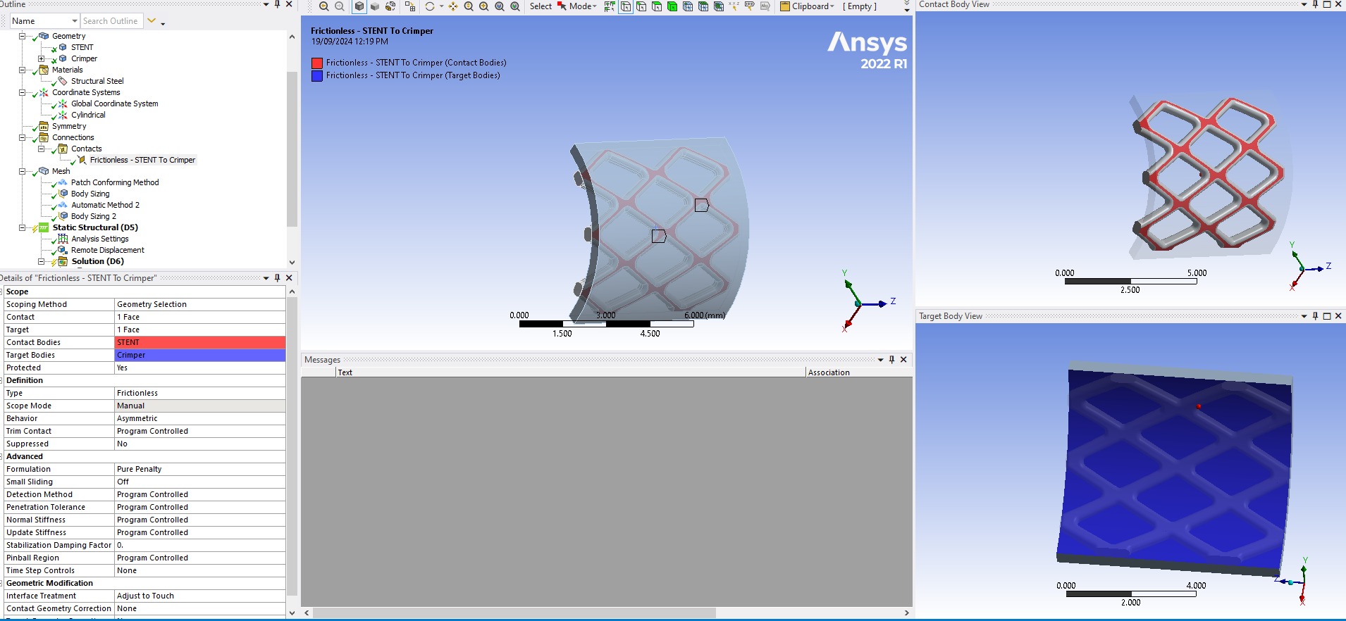
- The interaction between the inner surface of the crimping head and the stent's external surface is assumed to be frictionless.
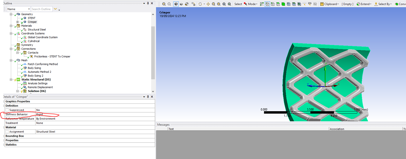
- A remote displacement is applied to a node at the center of each stent to prevent rigid body movement. (by following figure 👇)
Initially, I defined the crimper material as rigid and manually created a cylindrical coordinate system for radial displacement. I also set the interaction between the inner surface of the crimping head and the stent as frictionless. However, I encountered an issue where normal displacement could not be activated on the inner rigid body surface. To address this, I used a remote displacement with rigid behavior and tried changing the global coordinate system to the created cylindrical coordinate system which is not working. Even, cylindrical support does not work on the rigid body's face.
Could you please advise on how to correctly input the radial displacement boundary condition on the rigid body in this scenario? 🙏
Thank you in advance for your assistance.
-
September 19, 2024 at 12:18 pm
ErKo
Ansys EmployeeHi
As you found out it is not possible to do that (rigid part+remote disp.+cyl. system and radial displ.).
No bodies are fully/100% rigid, especially for contact situations they should not be – perhaps for rigid dynamics rigid might be ok in certain cases – so set that part to flexible.
Then the way to do what you want, is as we said to have a normal flexible body, and apply a radial displacement with a user defined cylindrical. sys. (located at centre line of pipe), and a displacement BC with the displ. in X (radial direction for a cylindrical system with Z along pipe centre line ).
All the best
Erik
-
September 25, 2024 at 2:14 am
f.yasmin
SubscriberThank you very much for your suggestion. I conducted the simulation by defining the previously rigid part as flexible and applying a radial displacement using a user-defined cylindrical coordinate system. The material for both the target cylindrical body and the contact stent body is set to stainless steel by default.
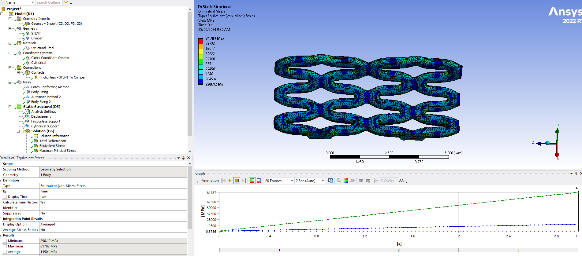
However, the equivalent Von Mises stress in the contact stent body is excessively high with just a 20% radial displacement (see the attached image 👇). I also tried different accepted geometries and materials, but the issue persists. Could you help me understand the possible cause for this?
Additionally, I am running this simulation model in Explicit Dynamics, where normal displacement can be activated on the inner rigid body surface via the user-defined cylindrical system (attached image 👇). My question is: would it be feasible to use Explicit Dynamics for my boundary condition (mentioned in my post)? Because, I am a quite beginner user of explicit.
-
- You must be logged in to reply to this topic.


-
4602
-
1510
-
1386
-
1209
-
1021

© 2025 Copyright ANSYS, Inc. All rights reserved.


