-
-
November 29, 2023 at 12:24 pm
Mariah Ha
SubscriberHi,Â
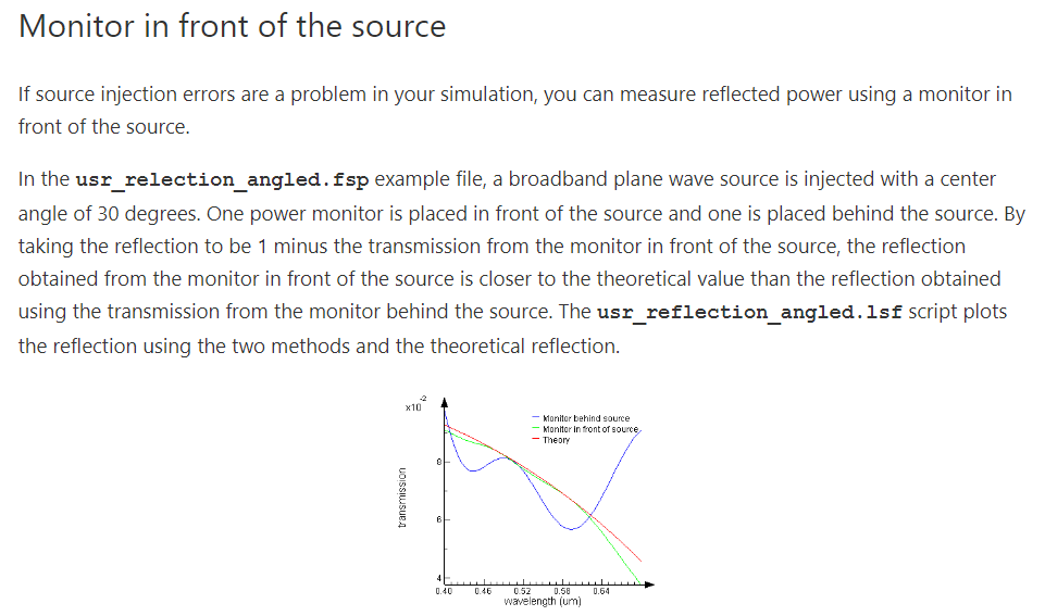
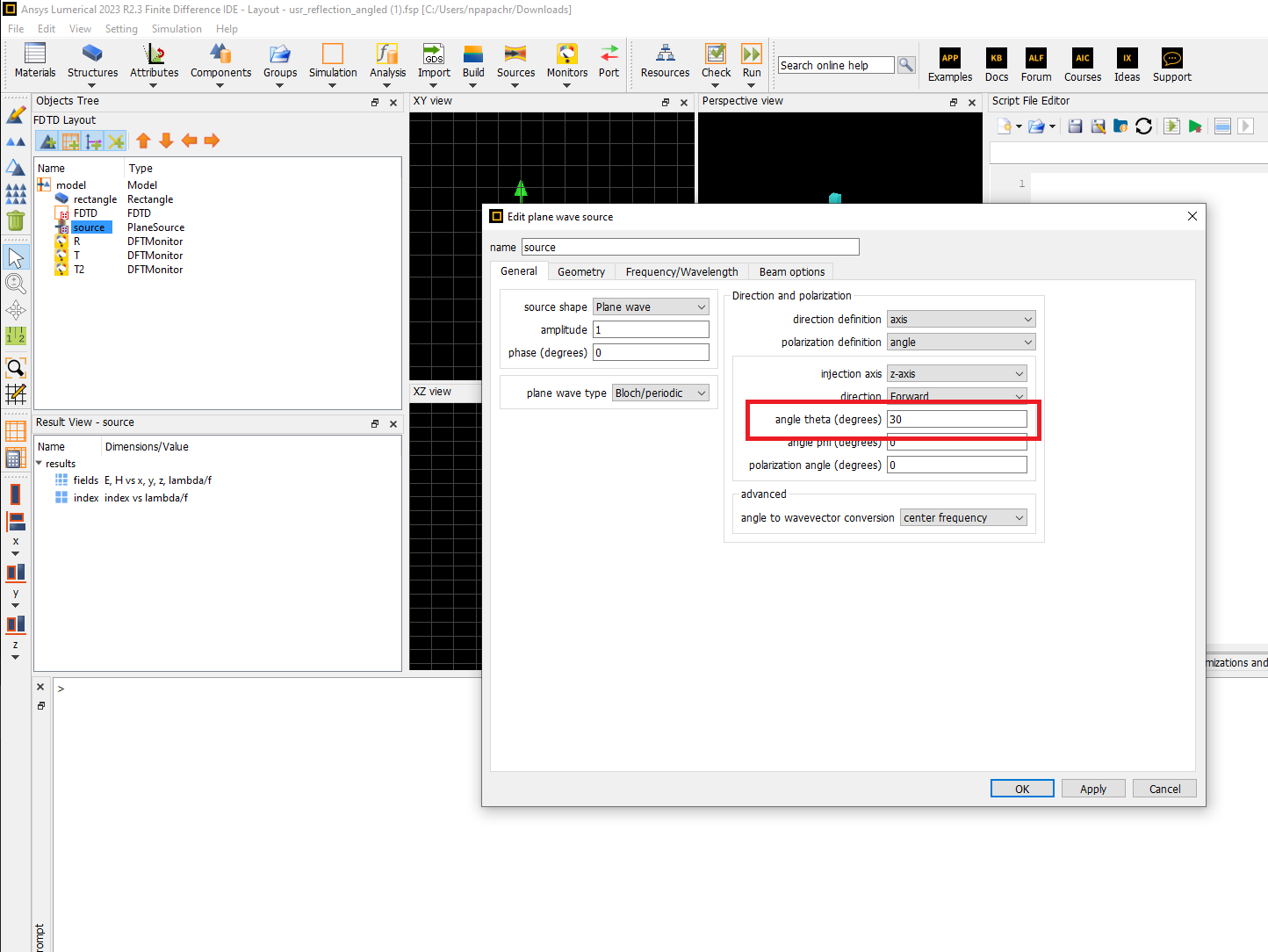
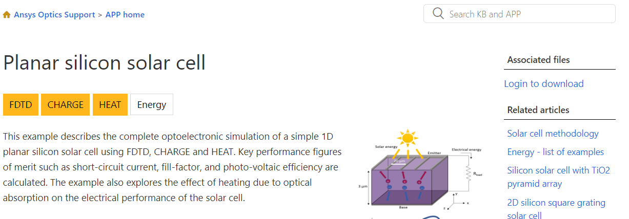
I have some questions regarding the "planar silicon solar cell" example of Lumerical. First, why is the reflection monitor placed in front of the source and not behind it although the source is planar with no injection angle (https://optics.ansys.com/hc/en-us/articles/360034915753-Tips-for-accurately-measuring-reflection-in-an-FDTD-simulation) ?Â
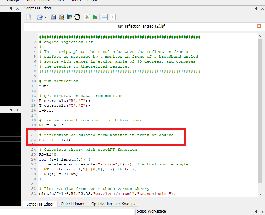
The second question is, why, in the script, it is written R=1+trnsmission("R") to calculate the reflection and not R=transmission("R")?
Thank you.
-
November 30, 2023 at 7:33 am
-
November 30, 2023 at 8:22 am
Mariah Ha
SubscriberThank you for the reply. The article suggests using the front monitor reflection when I have source injection errors, which come mainly from the injection at an angle. However, the solar cell example source is not injected at an angle and is a simple plane wave. This is why I was asking about the cause of using the front monitor for reflection in this case. The second point is, the article mentions taking the reflection 1 minus the transmission from the monitor. However, the script of the example takes 1+transmission. Could you please clarify these two points ? Thank you.
-
November 30, 2023 at 8:46 am
Niki Papachristou
Ansys EmployeeHi Mariah,
I downloaded the example and checked the sourse (right click and edit object), I confirmed that the injection angle is not 0 but 30 degrees (still a plane wave):
I also checked the script and again it seems that the reflection equation is as described on the article R2=1-T.T:
Kind Regards,
Niki
-
November 30, 2023 at 8:56 am
-
November 30, 2023 at 9:21 am
Niki Papachristou
Ansys EmployeeHi Mariah,
Thank you for the clarification. I believe that for the solar cell example is set up this way to cover both aspects. The fact that it is recomended to put the monitor infront of the source when the planewave has an angle does not cancel the case were the angle is 0. This way the users will be able to use the same example when they will need to inject the source with an angle. As for the 1+transmission equation in this case, I think that the transmission has negative values in its data base already.
Kind Regards,
Niki
-
November 30, 2023 at 9:37 am
Mariah Ha
Subscriberthank you for the clear answer. Just one more thing, now if I have a photodiode example, based on this solar cell example, I can place the reflection monitor either way front or back and change the scripting accordingly? ( R=transmission(R) for back monitor, and R=1-transmission(R)Â in front monitor case) .Â
-
November 30, 2023 at 1:51 pm
Niki Papachristou
Ansys EmployeeHi Mariah,
I think you are correct. You can always doublecheck the values (or the better the sign) of your Transmission by visualising them, before working on the script.
-
- The topic ‘Questions regarding an example’ is closed to new replies.
- Difference between answers in version 2024 and 2017 lumerical mode solution
- Import material .txt file with script
- Absorption cross-section of AuNR excited by prism-based TIR
- How to measure transmission coefficients on a given plane .
- TE Polarization Fraction + Waveguide TE/TM Fraction
- Edge Coupler EME Example Issue
- 2D inverse design grating coupler
- Lumerical Python API Topology Optimization Error 2025 R1
- FDE : Simulation waveguides with electrodes
- Loss of lithium niobate phase modulator
-
2537
-
933
-
787
-
599
-
591
© 2025 Copyright ANSYS, Inc. All rights reserved.