TAGGED: -quasi-static, mechanical, structures, transient, workbench
-
-
February 23, 2024 at 12:32 pm
Daming Wang
Subscriber
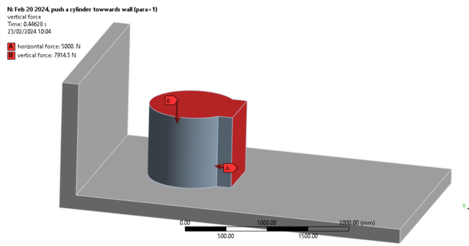
I've been doing some research on the Gap contact issue. For example, a cylinder is subjected to a horizontal(and vertical) load. In real life, I might not know if the cylinder would touch the wall, however, when it happens, I hope to obtain the stress/deformation of the cylinder. I assume at that time point, the cylinder firmly touched the wall, just like there is no initial gap between the cylinder and the wall.Â
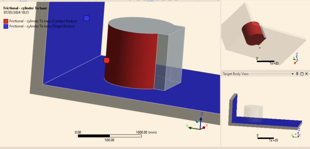
So I made a model, the idea of this case is that the cylinder and the wall initially have a distance and due to the horizontal load, the cylinder eventually touches the wall. The contact types are frictional (frictional parameter=0.2) and the horizontal force is higher than the frictional force due to the vertical force so the cylinder will be pushed towards the wall.
From my imagination, when the same force is applied to the cylinder. The final results (Von Mises stress and deformation) of the cylinder and the wall shall be identical no matter whether the cylinder and the wall initially touch each other or not.
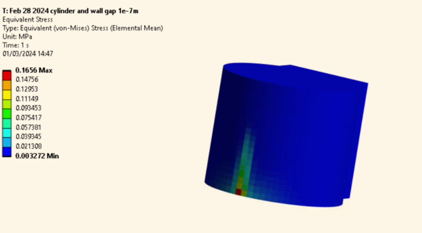
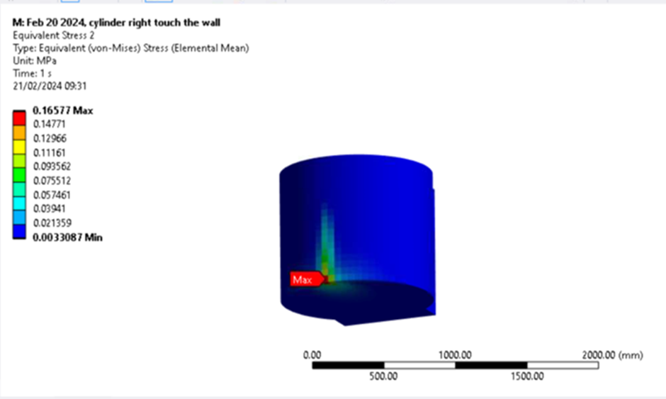
So I chose Static Structural system, in Analysis settings, I turned on "Quasi-Static Solution". I firstly made a system with zero distance and obtained the results. The stress distribution of the cylinder is shown below. We can see the max Von Mises stress is about 0.165Mpa.Â
Â
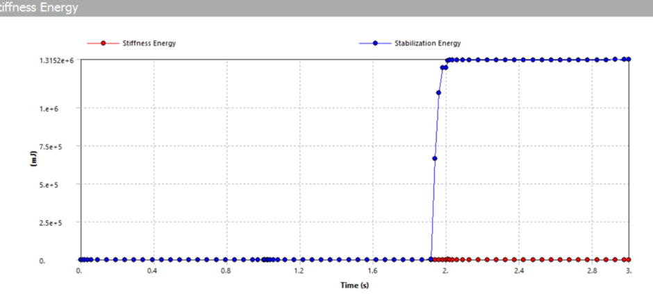
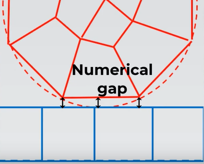
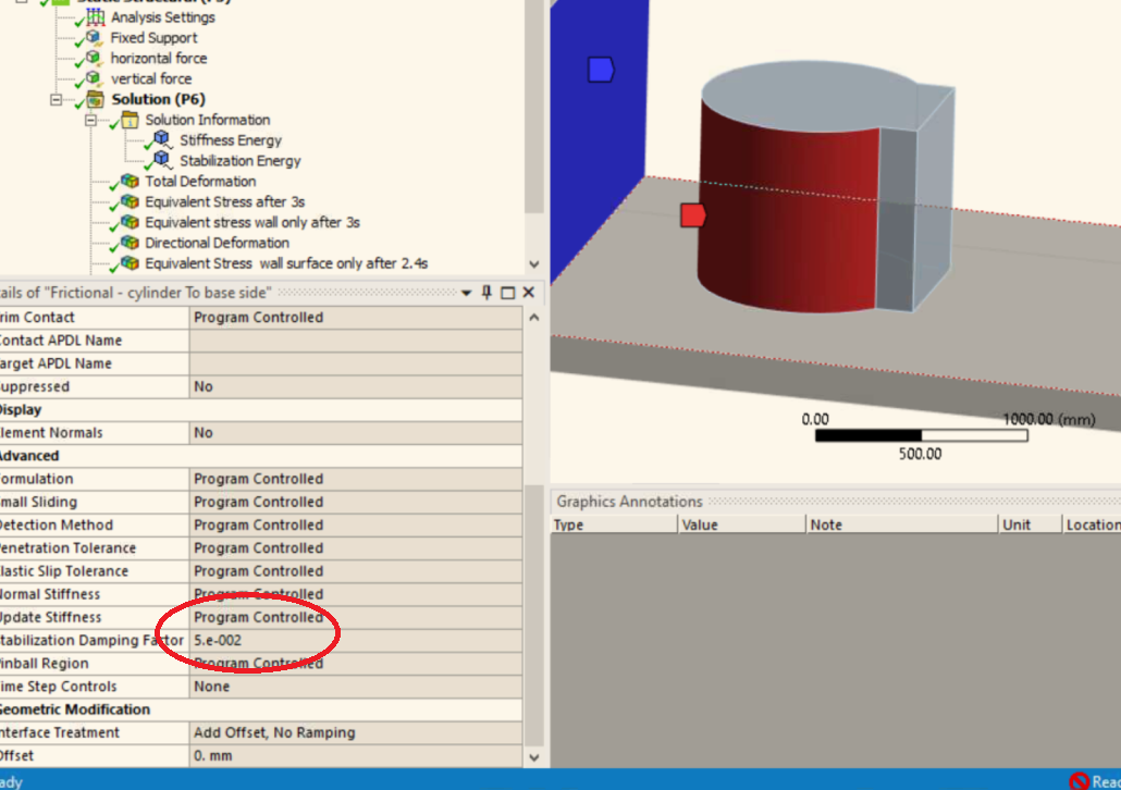
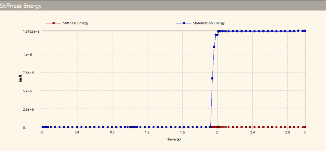
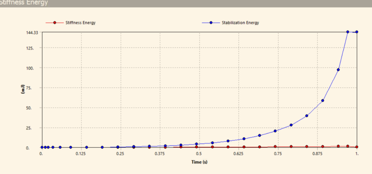
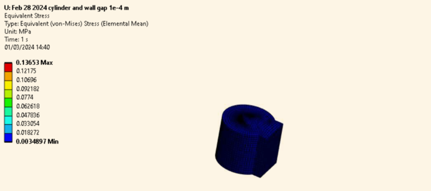
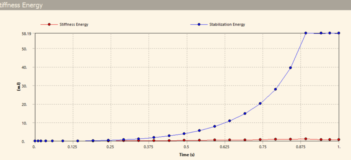
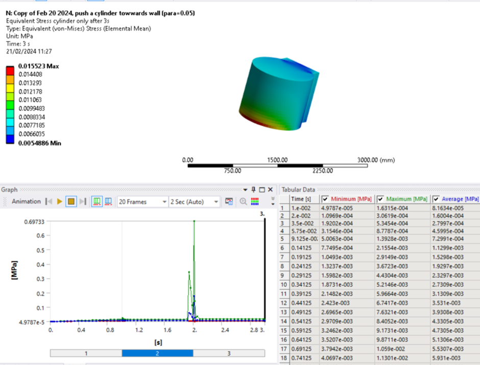
Secondly, I made a new system, this time, I deliberately made the distance between the cylinder and the wall to be 0.6m. The contact type, the load applied remained the same. I used the "Stabilization Damping Parameter=1.0" to make sure the gap contact between the wall and the cylinder can be simulated successfully. After calculation, the Von Mises stress on the cylinder is only 0.015Mpa, I don't why there is so much difference ,see the figure below:
Â
I got confused by the difference in the results. Do you know how I can obtain the same results in the Gap contact analysis as the system with no initial gap? I want to ignore any impact or dynamic effects.Â
Â
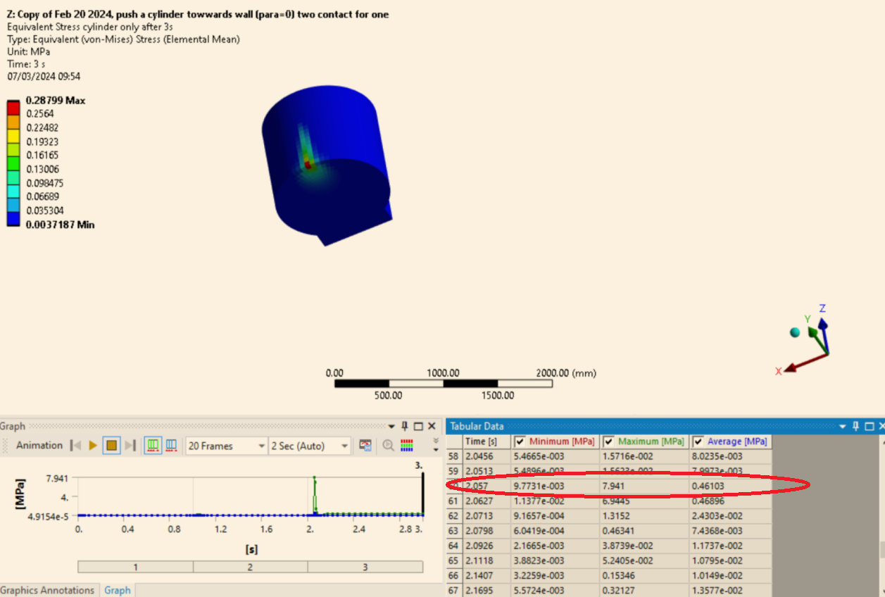
Also I found although I turned on the "Quasi-Static Solution", there is visible acceleration of the cylinder with time, see the figure, which is the total deformation below:
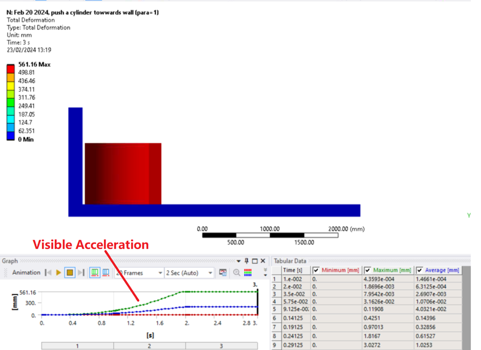
Do you know if the "Quasi Static Solution" neglects all of the accelerations?
Â
Â
Best regards,
Â
Daming
-
February 23, 2024 at 12:35 pm
-
February 24, 2024 at 2:15 am
peteroznewman
SubscriberTo get valid stress results in a Static Structural analysis, put the cylinder tangent to the wall using CAD or Part Transform. Right click on the Connections folder and Insert a Contact Tool. Right click on the Contact tool and select Generate Initial Contact Status. Examine the table for the Initial Contact Status of the frictional contact and confirm that it is Closed. Now you can Solve the Static Structural analysis. If the Initial Contact Status is Near Open, the gap will be extremely small. Under the Frictional Contact, you can set the treatment to Adjust to Touch. This will close that extremely small gap and you can get valid stress results.
The Quasi-Static setting is not intended to be used with a massive 0.6 m gap. It could be used on a 1e-5 m gap, but Adjust to Touch is a better option.
An accurate way to simulate a 0.6 m gap is to use a Transient Structural analysis. In this case you should do a hand calculation on the impact velocity given the acceleration due to the applied force. Again, put the moving object tangent to the wall and assign a Velocity Initial Condition and let the transients of the impact be calculated without wasting any computational effort accelerating the object up to the point of impact.
-
February 26, 2024 at 8:35 am
Daming Wang
SubscriberHi Peter, thank you so much for you reply. As I stated, I already obtained the correct results by placing the cylinder tangent to the wall using CAD software. In this condition, the max Von Mises stress from ANSYS simulation is 0.165Mpa as shown in the figure. However, I want to obtain the same results by delibrately placing the cylinder away from the wall. The reason is that in reality, the cyliner could be applied a horizontal force. when the force is small, the cylinder will not move. In this case, the wall will not have any influence on the final results. In a different case, when the force is large, the cylinder will move towards the wall and eventually stop there. I'm not concerned about the movement of the cyliner or impact force or acceleration. I'm only interested in the stress distribution of the cylinder when it reached the wall and the stopped there, with the force applied unchanged. Do you know how I can get it? Right now, I see clearly from ANSYS simulation that the cylinder moved from 0.6m away and stopped close to the wall. But I found the final Von Mises result is only 10% of 0.165Mpa, which made me confused. Â
-
-
February 26, 2024 at 12:01 pm
peteroznewman
SubscriberHere is a paragraph from the ANSYS Help page on Stabilization.
Note the word "artificial". The artificial dampers that you inapproprately added to your model are causing artificial forces to act on all the nodes in the system. When all the nodes see the same force, no stress is generated. Only a small amount of contact force is needed at the wall to balance the applied force and the opposing artificial forces, which causes only 10% of the stress of the true solution obtained by placing the cylinder tangent to the wall.
There are many ways to misuse the software to get wrong answers and by using your imagination, you have found another one.
-
February 27, 2024 at 8:28 am
Daming Wang
SubscriberHi Peter, thanks a lot for the info. However, I didn't use the nonlinear stabilization damping, which can be used for the whole system (on every node) and to reduce the global instabilities such as solve buckling issues. What I used in my run is the "Contact Stablization Damping Parameter" , which is defined only in the contact pair, not in the whole system. The "Contact Stablization Damping parameter" is used to solve the problem with initial distance between the "contact face" and "target face". Without this parameter, the run will not converge.Â
Please have a look at this video that expalined the differences between the global nonlinear stablizaton damping and the contact stablization damping parameter :
&t=1s  from 5:39, see the figure below:
-
-
February 28, 2024 at 11:58 am
peteroznewman
SubscriberI watched the video and suggest you rewatch the video and notice the following…
A.) Gaps should be handled in this order: 1) Move CAD parts to be tangent. 2) Use Adjust to Touch. 3) Use Contact Stabilization.
B.) Gaps are small, such as clearances between a pin and a hole or a numerical gap after meshing.
C.) Contact Stabilization creates Artificial Energy, it does not reflect reality and has no physical basis. There is no easy way to choose a Stabilization Damping Factor. The amount of stabilization energy must be compared with the stiffness energy to know that the artificial energy is an insignificant percentage of the stiffness energy. If it is significant, you must reduce the Stabilization Damping Factor. The Stabilization Damping Factor used in the video was 0.05.
You choose a value of 1.0 for the Stabilization Damping Factor and made the plot showing stabilization energy was huge compared to the stiffness energy. The conclusion you should draw is that the solution is garbage and you must reduce the Stabilization Damping Factor.
-
February 28, 2024 at 1:25 pm
Daming Wang
SubscriberHi Peter, thank you for your reply. I actually already tried the Stablization Damping Paramter=0.05, the result was as terrible as the result with Damping Parameter=1. Plz see the figure below:
The Stiffness energy vs Stablization energy is as bad as the previous run with para=1. See the figure below:
It can be noticed the Stablization energy is almost identical with the one with para=1.
-
February 28, 2024 at 1:40 pm
Daming Wang
SubscriberHi Peter, I actually used the "adjust to touch" in other projects and it works fine. I made the CAD files myself and I know how to place the bodies with zero distances to make sure the analysis can be finished without using any Contact Stablization Damping Paramter. The purpose of the this post is to see if cases from my discription (with inital distance and eventually contact each other with forces still applied) can be finished with the correct results.Â
-
-
February 28, 2024 at 4:16 pm
peteroznewman
SubscriberAs the video says, there is no algorithm to choose a good value of the Stabilization Damping Factor, there is nothing special about 0.05. You might need 1e-4 or smaller. At some point the solver will fail to converge. What is known is to make the plot you made to know that the results are garbage and the SDF is too large.
Contact Stablization was designed to treat small gaps. You are testing it with a large distance that would have been unthinkable to the developers. Since you know how to move the CAD and use Adjust to Touch and are only trying to learn the limits of Contact Stablilization, I suggest you try a gap of 1e-4 m instead of 0.6 m and see if the Stabilization Energy becomes much smaller.
-
February 29, 2024 at 8:05 am
Daming Wang
SubscriberThank you, I will make a new run as suggested.
-
March 1, 2024 at 1:58 pm
Daming Wang
Subscriber
-
-
March 1, 2024 at 7:33 pm
peteroznewman
SubscriberGreat, now reduce by a factor of 10, 100, 1000 the Stabilization Damping Factor until the Stabilization Energy is less than the Stiffness Energy at the end of the solution, or until the solution fails to converge.
-
March 7, 2024 at 9:24 am
Daming Wang
SubscriberHi Peter, I decided to solve this problem by turning to a new direction. I think it is not a good idea to solve the gap contact problem in a unstable system using "contact Stablization Damping Factor". As we know, the cylinder is un-restrained relative to the wall.ÂÂÂÂThis time I combined the 2 contact pairs (one pair for the contact between the cylinder bottom and the base face, the other is the side of the cylinder and the side of the wall) into only one contact pair, see the figure below. The contact type is frictional with frictional coefficient of 0.2. The load applied on the cylinder is unchanged. The initial distance between the cylinder and the wall is 0.6m. The stablization damping factor is 0.ÂThe run was finished successfully. I can see clearly the cylinder moves towards the wall and stopped there. This time, when the cylinder hits the wall, there is a extremely large stress spike, which is 7.9Mpa, which is reasonable. It can be seen from the figure below that the cylinder hits the wall at 2.057s.ÂSince the load is still applied, I thought the Von Mises stress should drop and reached the same value as the case previously mentioned with zero initial distance between the cylinder and the wall (0.16Mpa). However, from the figure above, we can see the maximum Von Mises stress after the hit remains at 0.287Mpa until the end of the simulaton (t=3s), which is much higher than 0.16Mpa.ÂÂÂÂDo you know what caused the differnece?
-
- The topic ‘Questions about the Static/Quasi-Static/Dynamic’ is closed to new replies.
-
3492
-
1057
-
1051
-
965
-
942
© 2025 Copyright ANSYS, Inc. All rights reserved.