-
-
March 5, 2024 at 9:04 am
Miller Testing
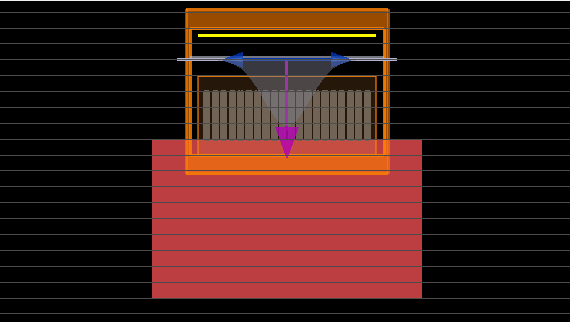
SubscriberI had a structure and I want to run the simulation on that structure in the FDTD.
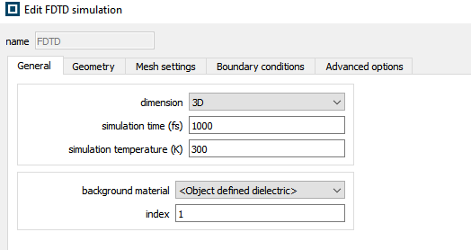
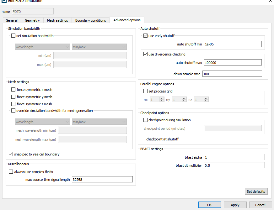
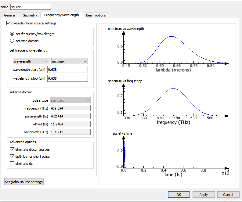
I use the default auto shut off value which is 1e-05, I use gaussian source with 638nm, and when I tried to run the simulation,
I got this for the log
Estimate of memory required: 1.08786e+10 bytesnumber of processors is 16processors are distributed as: 4x4x1Peak memory used by end of initialization: 7579837 kBRunning 3D SimulationStarting meshingSimulation size in gridpoints: 388 x 388 x 70Refined 0 mesh cells (0%)Completed meshing!Meshing complete in 4.35938 seconds of CPU time38336 38336Starting meshingSimulation size in gridpoints: 388 x 388 x 70Refined 0 mesh cells (0%)Completed meshing!Meshing complete in 4.23438 seconds of CPU time38376 38376Starting meshingSimulation size in gridpoints: 388 x 388 x 70Refined 0 mesh cells (0%)Completed meshing!Meshing complete in 4.23438 seconds of CPU time76248 76248finished material propertiesMeshing Time: 17.3542 seconds, Init Electrical Material Time: 3.58265 seconds, Init Magnetic Material Time: 0.0525491Using selected optimization level: 2Selecting 3d kernel for splitFieldDirection=0 and optLevel=2-----------------------------------------Beginning initialization of 3D SimulationStarting to add sources to simulationAdding 3D Gaussian source propagating in ZStarting to add boundary conditions to simulationAdding 3D PML BCAdding 3D Parallel BCAdding 3D PML BCAdding 3D Parallel BCAdding 3D PML BCAdding 3D PML BCStarting to add monitors to SimulationAdding analysis monitorAdding analysis monitorAdding 3D DFT monitorFinished initialization of 3D Simulation-----------------------------------------Peak memory used by end of meshing: 8611577 kBAll processes are communicating and ready to proceed to simulation...Starting 35123 total iterations0.0683311% complete. Elapsed simulation time: 6.83311e-16 secs. Max time remaining: 14 hrs, 3 mins, 47 secs. Auto Shutoff: 10.384362% complete. Elapsed simulation time: 3.84362e-15 secs. Max time remaining: 25 hrs, 42 mins, 57 secs. Auto Shutoff: 10.885457% complete. Elapsed simulation time: 8.85457e-15 secs. Max time remaining: 20 hrs, 26 mins, 16 secs. Auto Shutoff: 11.58016% complete. Elapsed simulation time: 1.58016e-14 secs. Max time remaining: 16 hrs, 35 mins, 3 secs. Auto Shutoff: 12.38874% complete. Elapsed simulation time: 2.38874e-14 secs. Max time remaining: 14 hrs, 17 mins, 29 secs. Auto Shutoff: 12.94108% complete. Elapsed simulation time: 2.94108e-14 secs. Max time remaining: 14 hrs, 18 mins, 5 secs. Auto Shutoff: 0.001249133.31975% complete. Elapsed simulation time: 3.31975e-14 secs. Max time remaining: 15 hrs, 3 mins, 58 secs. Auto Shutoff: 0.0001788783.71266% complete. Elapsed simulation time: 3.71266e-14 secs. Max time remaining: 15 hrs, 34 mins, 59 secs. Auto Shutoff: 8.52056e-054.10271% complete. Elapsed simulation time: 4.10271e-14 secs. Max time remaining: 15 hrs, 59 mins, 40 secs. Auto Shutoff: 4.50694e-05100% complete. Max time remaining: 0 mins, 0 secs. Auto Shutoff: 8.59409e-06Early termination of simulation, the autoshutoff criteria are satisfied.Completed 1545 iterations, or 4.398813e-14s of Simulation TimePeak memory used running the simulation: 8611577 kBProcess 0 starting to collect datacollecting monitor datacollecting source dataFinished collecting dataSimulation completed successfully at: 週二 三月 5 12:16:09 2024Peak memory used in the simulation: 8611577 kBOverall wall time measurements in seconds: 2953.92time to mesh and initialize: 98.3486time to run FDTD simulation: 2724.54time to checkpoint simulation: 0time to finalize data and save to files: 61.6558miscellaneous time: 69.375FDTD solver speed on process 0: 5.9758 Mnodes/stotal FDTD solver speed on 16 processes: 95.6128 Mnodes/sit went from +- 4% into 100% directly or auto shut off, is it normal? and will it suffice for the simulation, I mean will it affected the output of the simulation, because right now I want to use that simulation to fetch the far field image from the monitor above the structure that I want to see and analyze the reflect of the wavelengths diffraction here.
Could someone help me explain this situation that I’ve encountered? And if there is anything or any information that you need for the explanation, feel free to ask me, as long as I can provide it.
PS: should I increase or decrease the auto shutoff value?
Thank you for the kind support.
-
March 5, 2024 at 8:05 pm
Amrita Pati
Ansys EmployeeHi,
It is hard to tell if this is expected or not. For certain geometries and source parameters, the auto shutoff can drop very quickly. In others, cases when the device is operating close to the resonant wavelength, it might take much longer for the fields to decay.
Do you see the expected results from your monitors? What is the mesh accuracy you are using? We usually recommend users to perform convergence testing to confirm the validity of results. I will recommend you to run the simulation with increasing mesh accuracy and see if the results converge.
Regards,
Amrita-
March 7, 2024 at 6:14 am
Miller Testing
SubscriberHi Amrita,
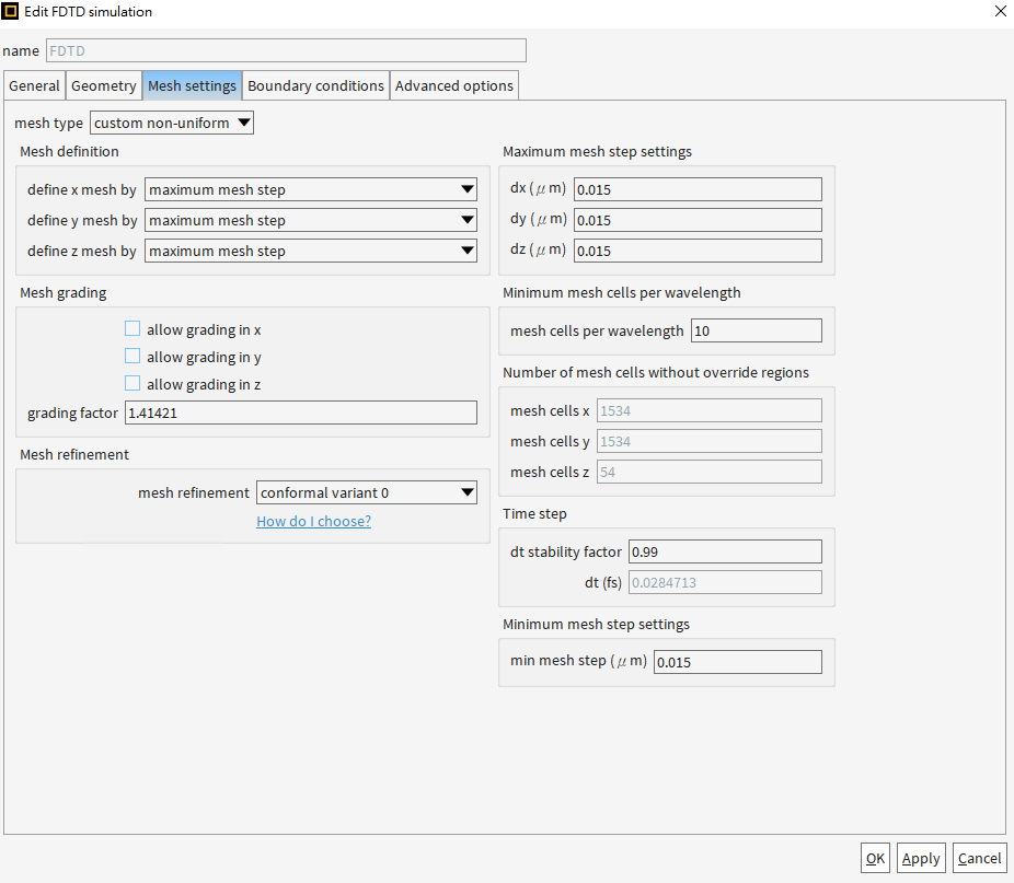
I did not see any mesh accuracy setting, because in the mesh setting, I use the custom non-uniform setting,
hence I did not see the mesh accuracy setting that I use.
and for the convergence testing, I had tried the example from the link that you provided to me,
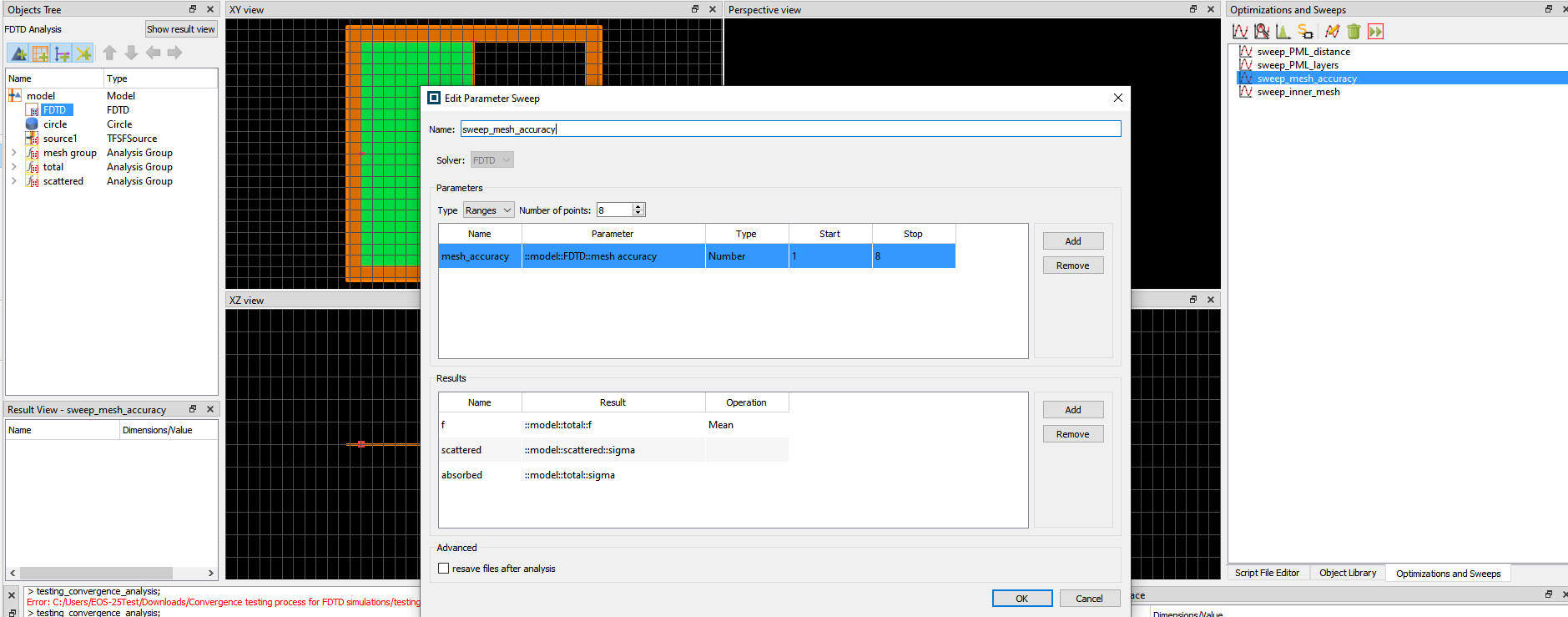
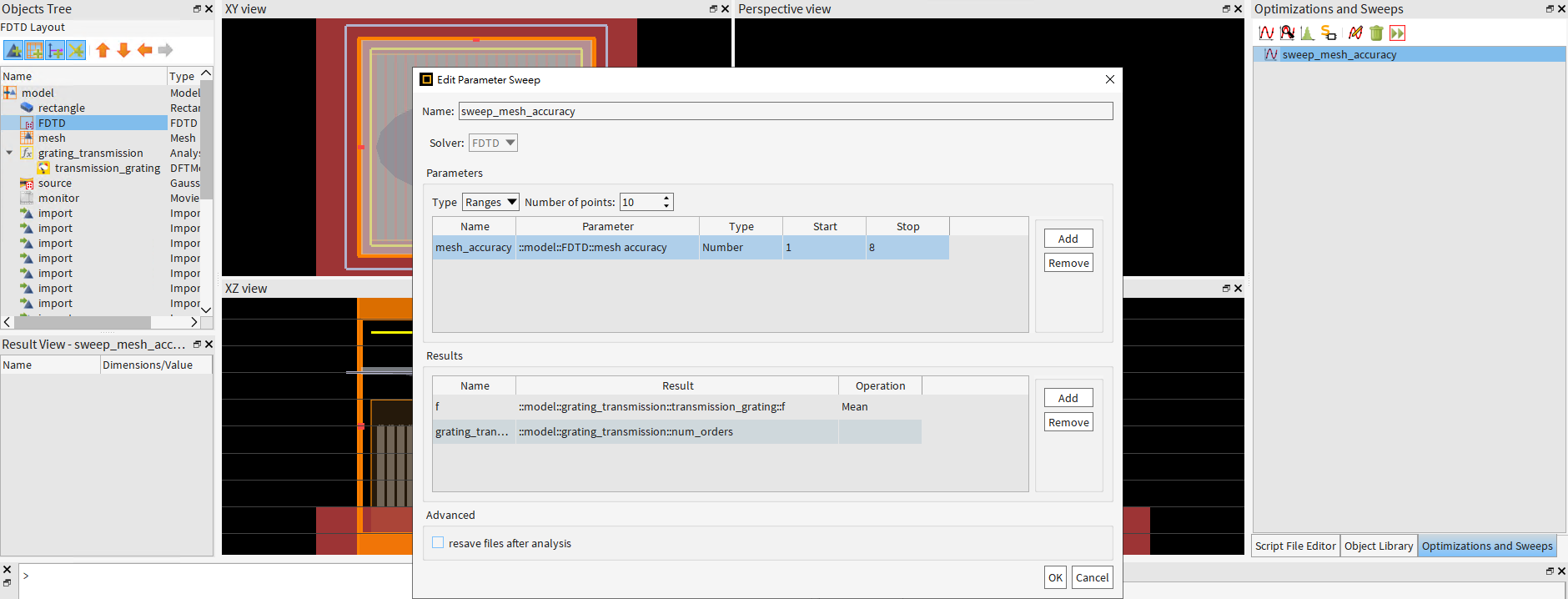
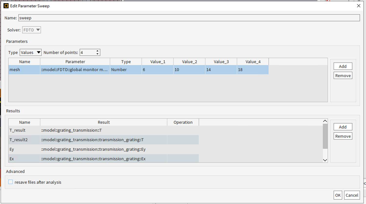
however, when I tried to do a convergence testing in my file by adding a sweep mesh accuracy parameters, I quite confuse, because there are no sigma in my grating_transmission function as show as the scattered function sigma in the example here. Is that affected by the amount of the dft monitors that we use in analysis function in the simulation? or the sigma inside the results of the parameters sweeps was added by using the script ?
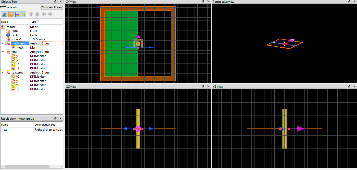
is there any different setting between the example and mine? because I saw the example are using 4 monitors each in the analysis function, while mine only using 1 dft monitor in my function analysis. below is the picture from the example of convergence testing. Is it have an effect to add new parameters such as sigma in the simulation, I mean 1 dft monitor will not show a sigma result parameters inside the parameter sweep parameters instead of 4 dft monitor that we use in the simulation?
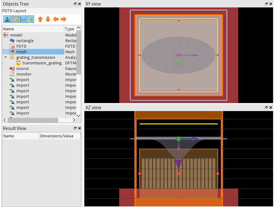
and this one is mine only use 1 dft monitor in my analysis function in my structure.
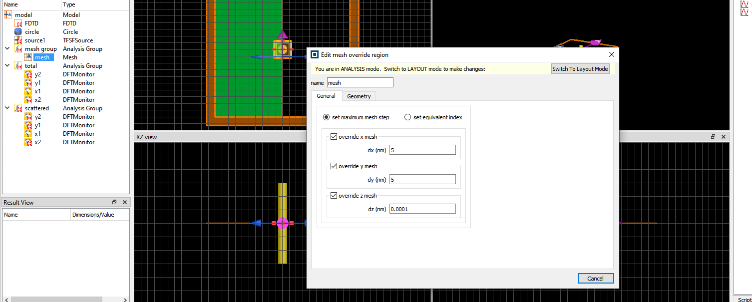
below is the example use the mesh dx, dy are 5 nm and dz is 0.0001 nm,
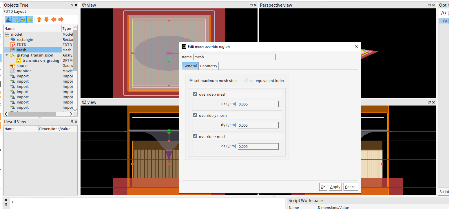
and mine is 0.005 nm for dx,dy and dz
can you help to guide me regarding the convergence testing here? I am still quite unfamiliar with the setting here.
Thank you for your kind support.
And I also found another explanation regarding my question here in this forum: /forum/forums/topic/question-about-autoshutoff-in-fdtd/
there are 4 links that are provided by Mr. Guilin Sun,
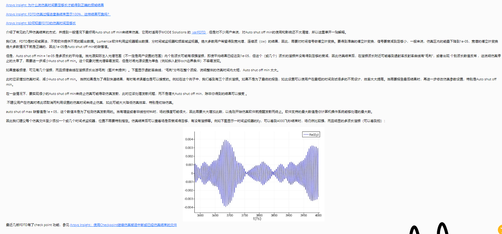
Ansys Insight: 为什么说仿真时间要足够长才能得到正确的频域结果
/forum/
Ansys Insight: FDTD仿真过程进度条结束显示100%,这样结果可靠吗?
/forum/forums/topic/ansys-insight-fdtdfangzhenguochengjindutiaojieshuxianshi100zheyangjieguokekaoma/
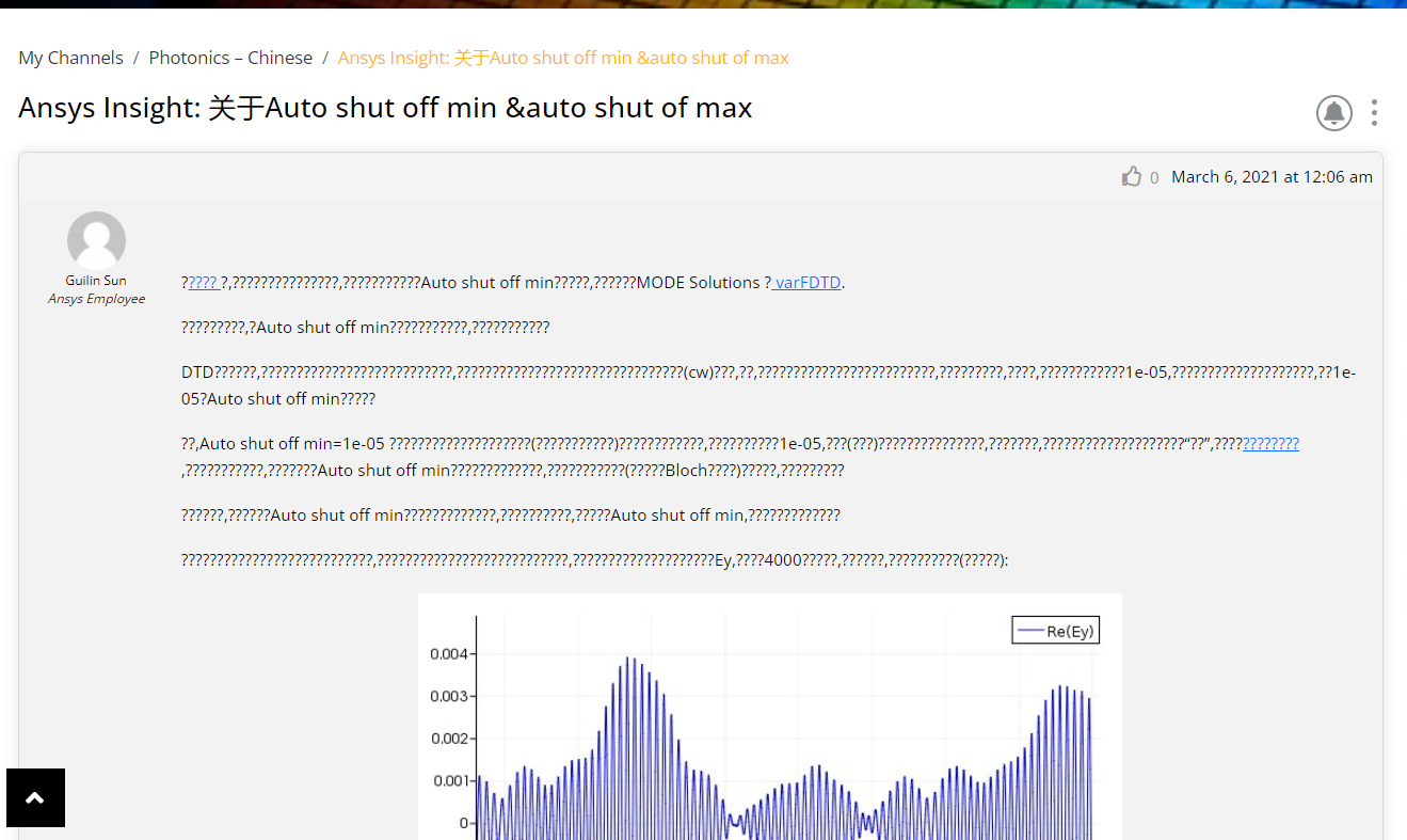
Ansys Insight: 关于Auto shut off min &auto shut of max
/forum/forums/topic/ansys-insight-%e5%85%b3%e4%ba%8eauto-shut-off-min-auto-shut-of-max/
Ansys Insight: 如何知道FDTD的仿真时间足够长
/forum/forums/topic/ansys-insight-%e5%a6%82%e4%bd%95%e7%9f%a5%e9%81%93fdtd%e7%9a%84%e4%bb%bf%e7%9c%9f%e6%97%b6%e9%97%b4%e8%b6%b3%e5%a4%9f%e9%95%bf/
I can open the 2nd, 3rd, and 4th links, but in the 3rd link, most of the words are “???”, therefore I did not know what kind of message or point that the Mr. Guilin Sun was trying to say. Can you help me clarify this?
and for the 1st link, it seems to be missing or nowhere to be found because it redirects me to a forum ansys homepage?
-
-
March 8, 2024 at 9:33 pm
Amrita Pati
Ansys EmployeeHi,
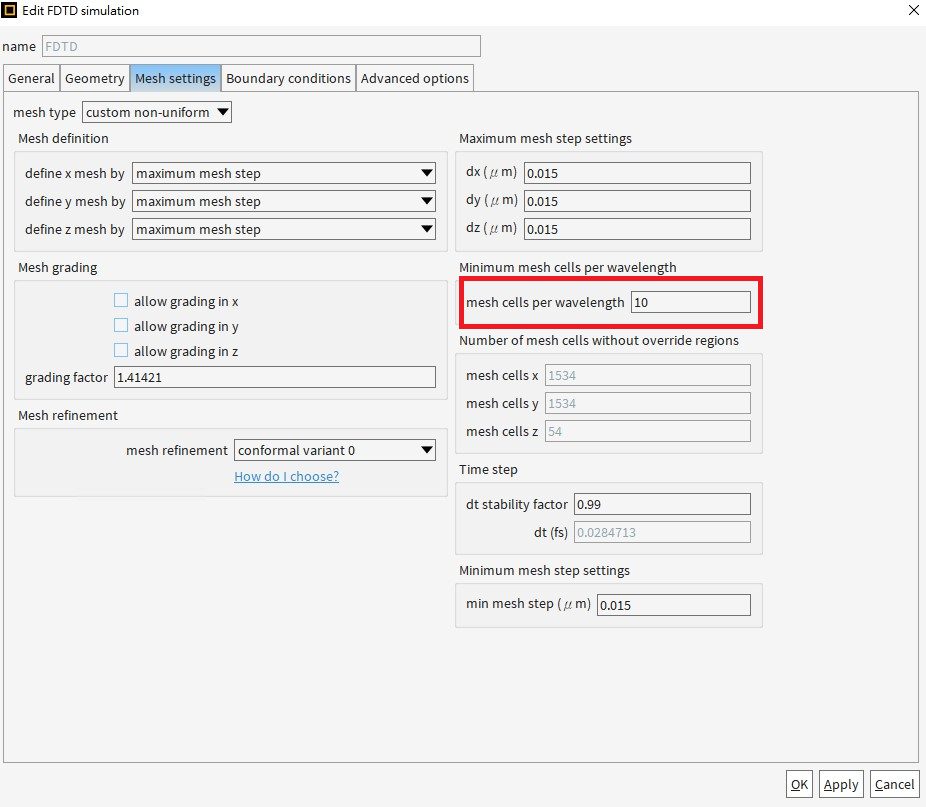
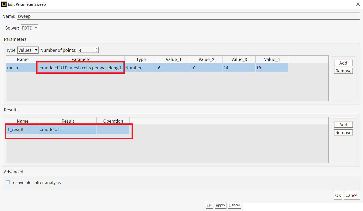
Since you are using a custom non-uniform mesh, you can change the mesh density by changing the number of mesh cells per wavelength.
Increasing the mesh will make the mesh denser. So, you will use this as the parameter for the sweep. For the result, you can use any result that maybe of interest to you. For example, you can check how the transmission or the reflection changes for different mesh accuracy. With increasing mech accuracy, they should look similar, which gives us more confidence on the results.
I saw Guilin's post. I will ask him about the first link. Would you be able to share a screenshot of your result (without convergence testing)? You need to reduce the auto shutoff typically only when you see oscillations in the transmission/reflection spectrum. Otherwise the default levels are good enough. I don't think it is an issue if the auto shutoff falls too quickly if you don't see any oscilations in the data.
Regards,
Amrita -
April 18, 2024 at 5:25 am
Miller Testing
SubscriberHello Amrita,
I apologize for my delayed response.
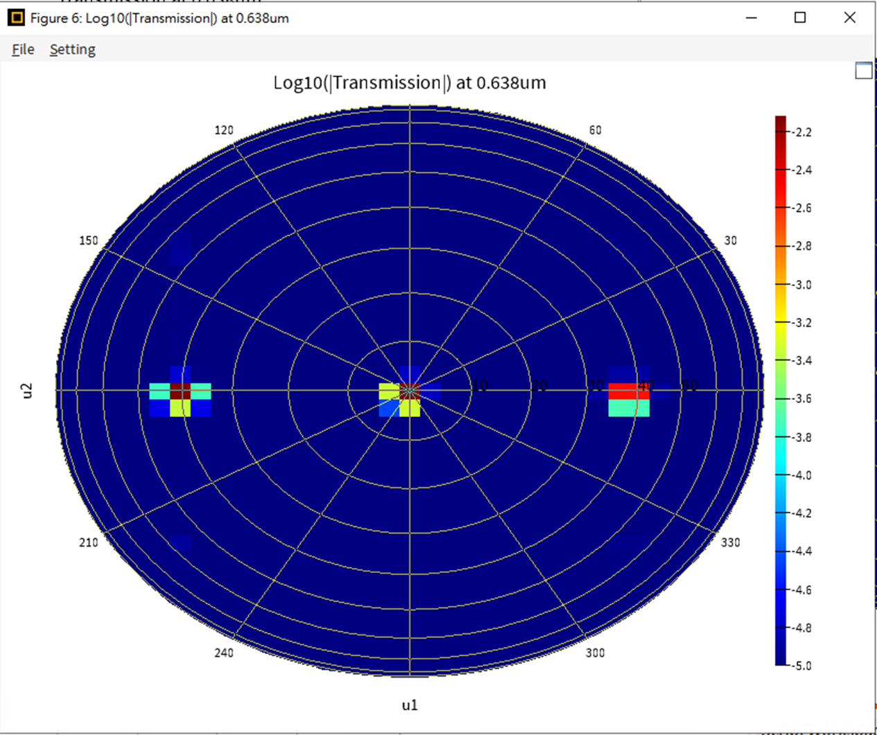
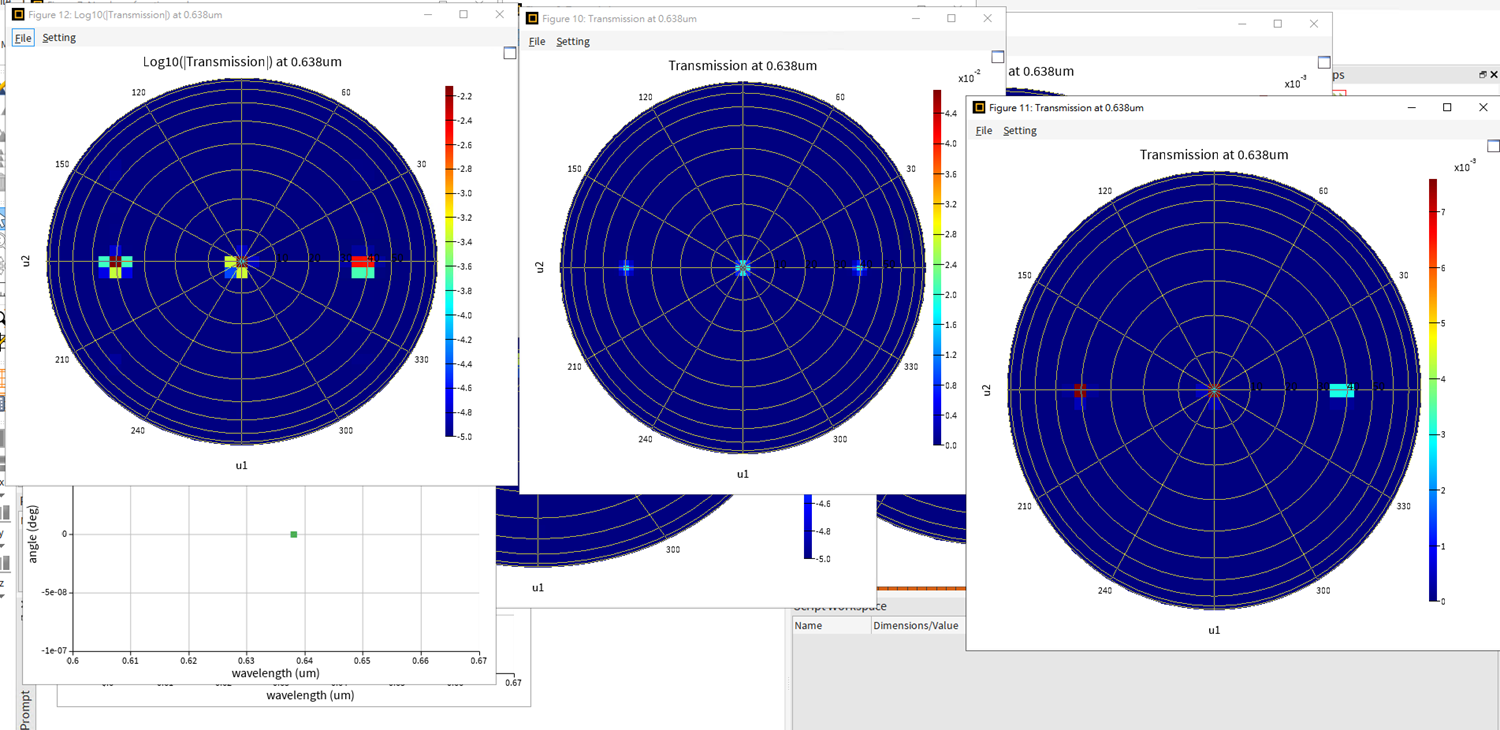
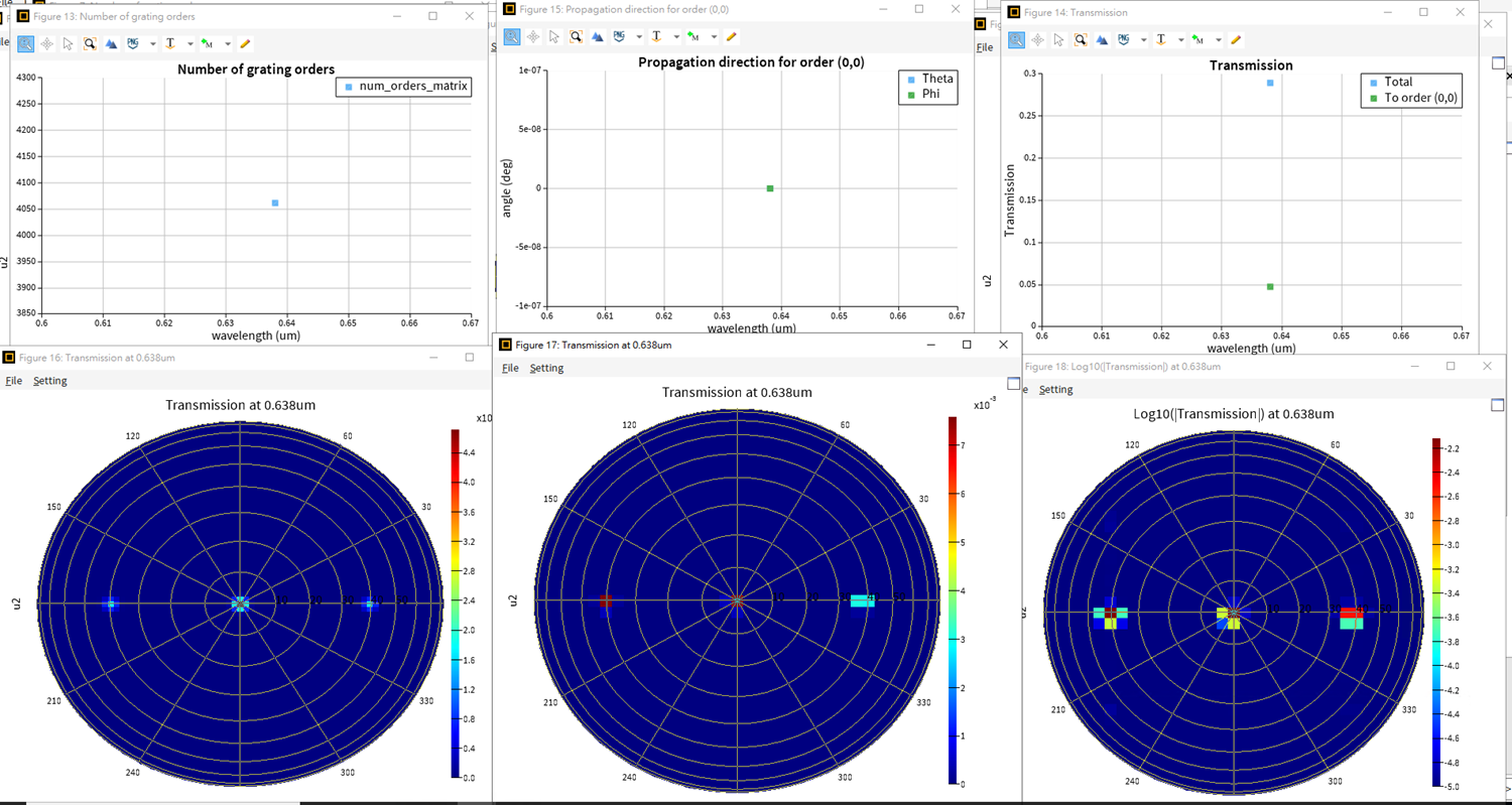
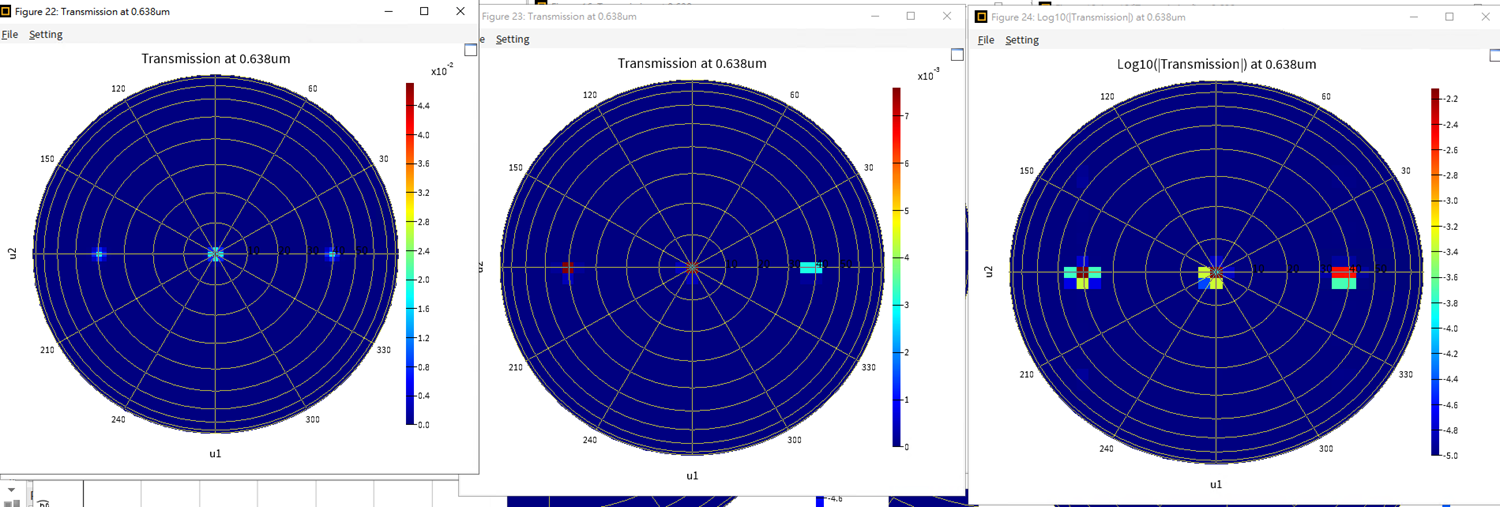
I adjusted the mesh density by changing the number of mesh cells per wavelength, using values like 6, 10, 14, and 18, as shown in the image you provided.
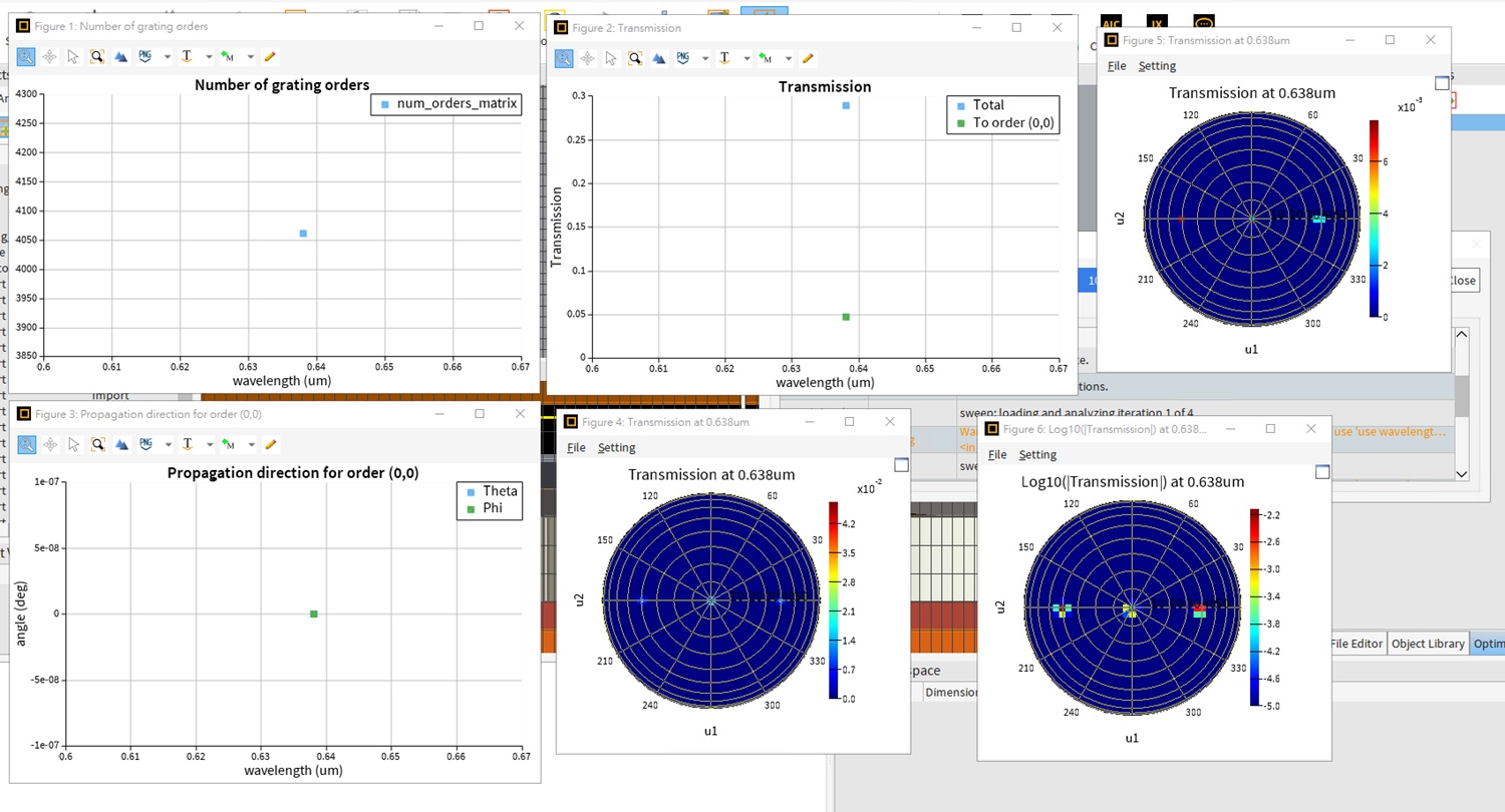
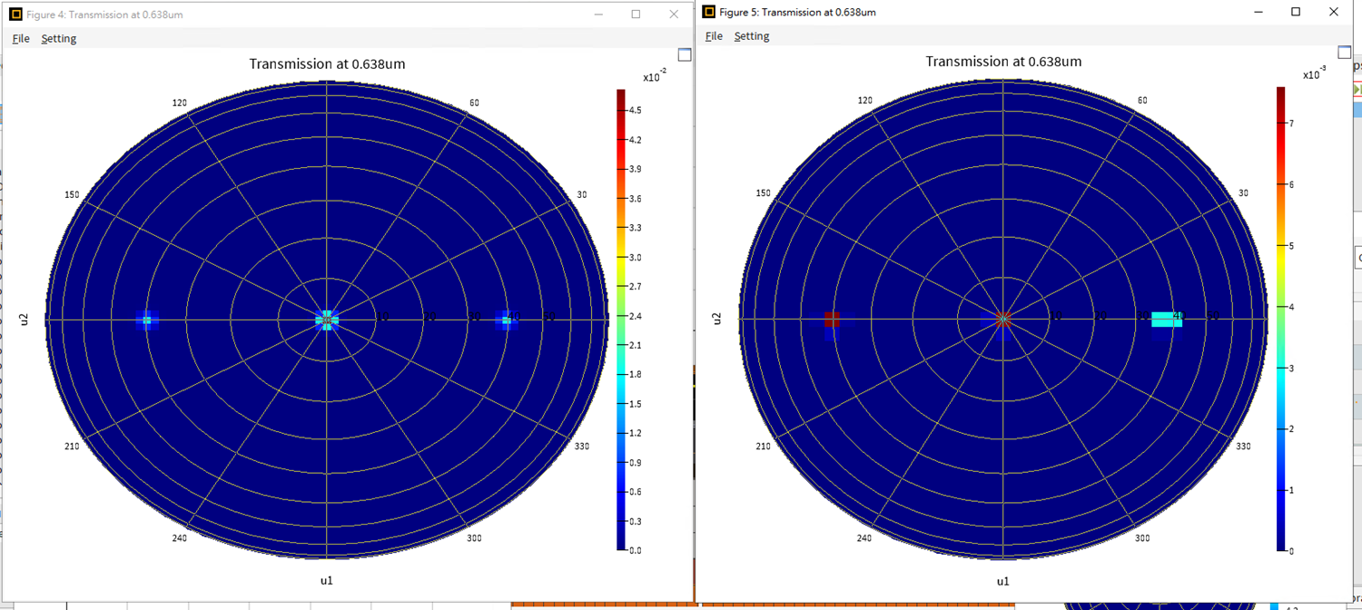
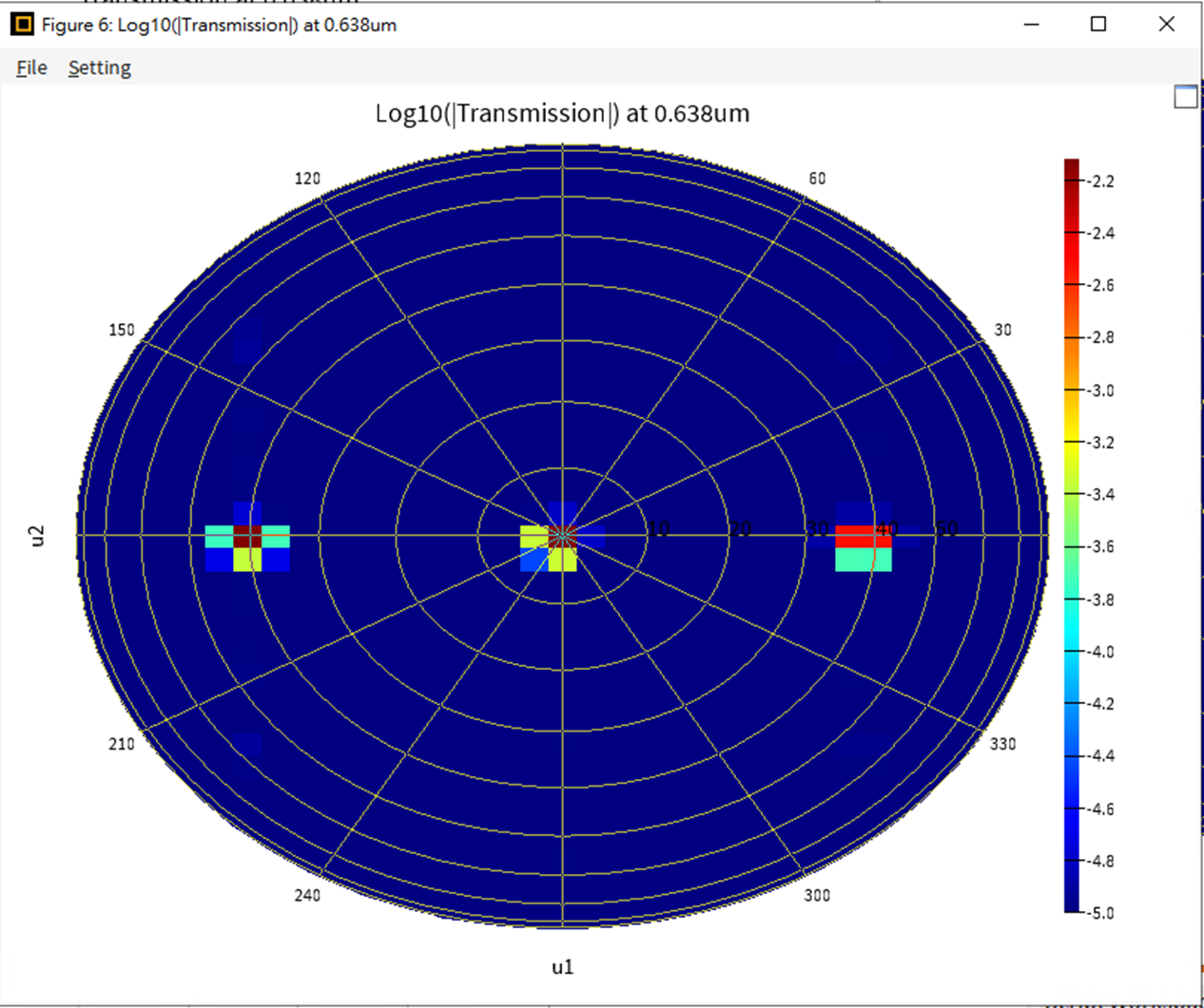
Regarding the results, I observed the changes in transmission using the sweep function:
1. with mesh value 62. with mesh value 103. with mesh value 144. with mesh value 18From my observations, the results are quite similar across mesh cell per wavelength values of 6, 10, 14, and 18. The reflectance angle is approximately 39 degrees, which is consistent with my calculations. The number of grating orders, transmission rates, and propagation directions for each order are nearly identical.
I am conducting simulations using a 638 nm wavelength with a top layer of SiO2 and a silicon substrate.
Do these results suggest that the simulation has converged and is sufficient for my needs?
Best regards, Miller.
-
April 18, 2024 at 6:55 pm
Guilin Sun
Ansys EmployeeHi Miller, I rewrote the first post and updated the 3rd post. Here are they:
Ansys Insight: 为什么说仿真时间要足够长才能得到正确的频域结果
ironically, once I used the exact same post title, the previous link was actIvated. Both the new and the old posts share the same link because it convert the title into the link.
Ansys Insight: 关于Auto shut off min &auto shut of max
-
April 19, 2024 at 8:38 am
Miller Testing
Subscriber
-
-
April 18, 2024 at 8:12 pm
Amrita Pati
Ansys EmployeeHi Miller,
This looks to me like it's converged. Ideally, for grating farfield it is advisable to more number of points rather than less. Otherwise in some cases, the intensity data can be smeared returning incorrect results. This so far looks good to me.
There is one additional thing you could do to make sure that the results are accurate.Sometimes, certain source wavelengths can be resonant wavelengths for the simulated geometry. In those cases, you might need to reduce the auto shutoff level further from the default (1e-05) to let's say 1e-07 and so on. It is easy to tell if there is a resonance from a broadband simulation since you will see a sharp transmission peak in the spectrum, often accompanied by some oscillations. Since this is just a single wavelength simulation, it is hard to tell.
What you can do is run a broadband simulation and collect the monitor results. For example, if you had a simulation at 0.55 um, you can try running a broadband simulation for 0.4 to 0.7 um. If you don't see a resonant peak at 0.55 um (in the broad-band simulation) or oscillations then you are good to go. But in case you do see them, you would have to reduce the auto shutoff level and rerun the simulation to see if the results change or converge similar to what you did for the mesh density.
Regards,
Amrita -
April 21, 2024 at 2:18 pm
Miller Testing
SubscriberHi Amrita,
Thank you for the confirmation.
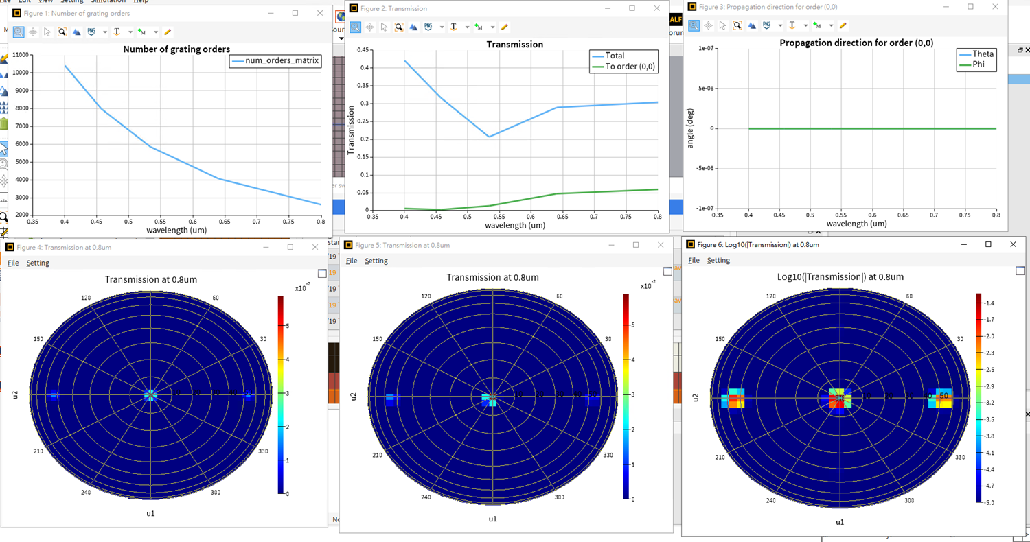
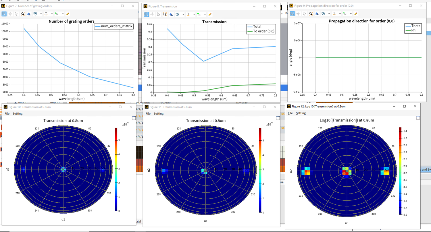
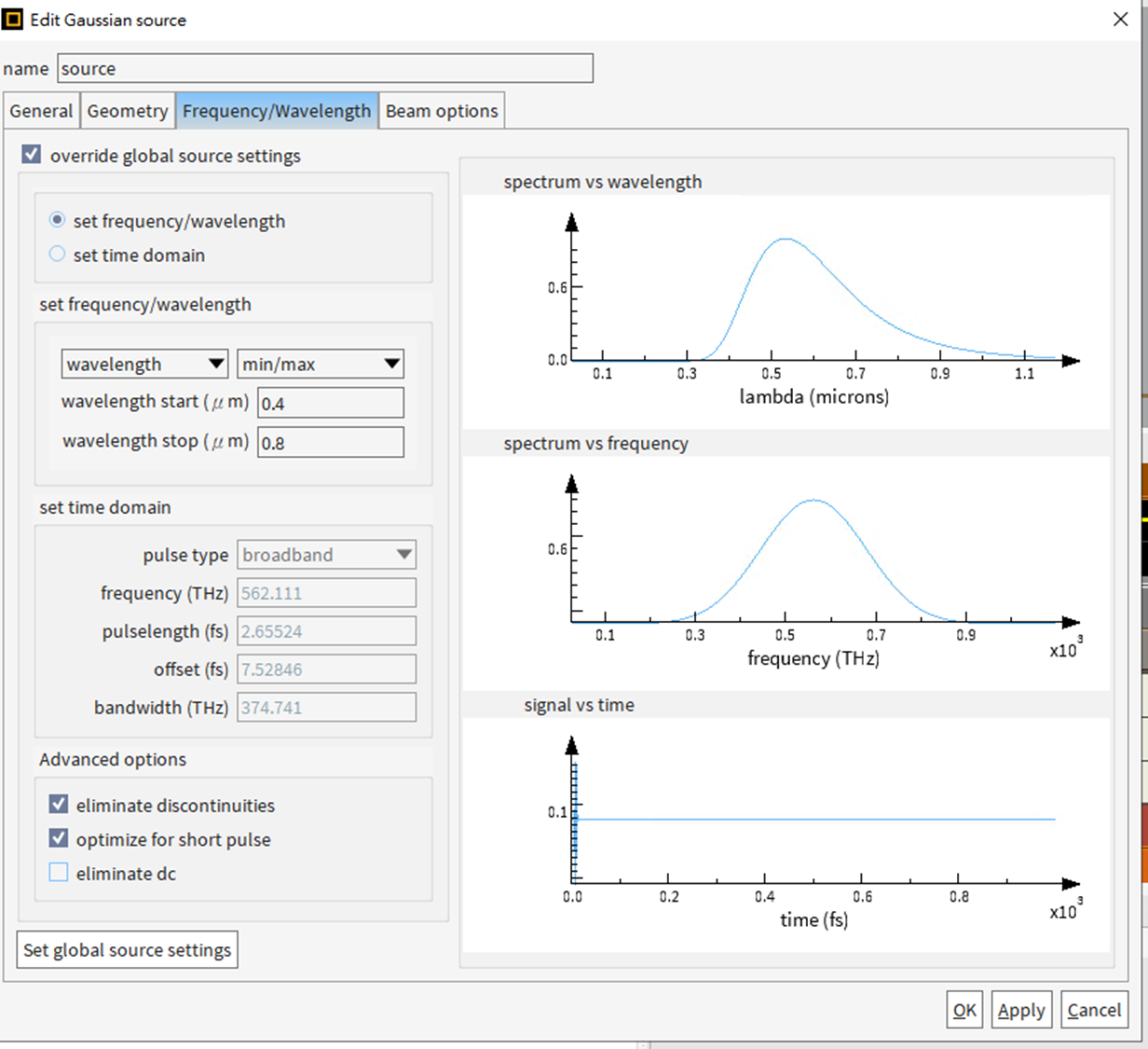
I attempted to run a broadband simulation for 0.4 to 0.8 micrometers using mesh cells per wavelength at 6, 10, 14, and 18. I did not change the auto shutoff level for this simulation and continued to use the default auto shutoff value, which is 1e-05.
Below are the results of the simulation:
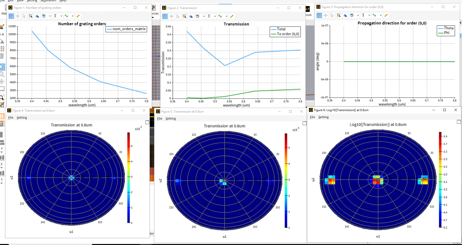
- Mesh cell 6:
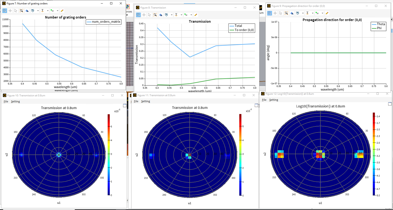
2. Mesh cell 10:
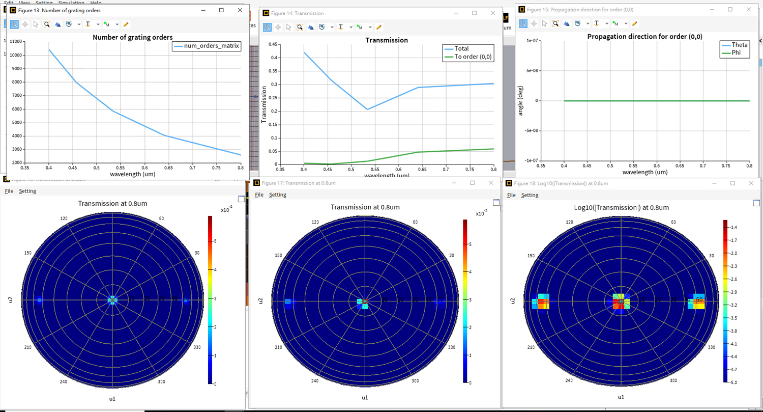
3. Mesh cell 14:
4. Mesh cell 18:
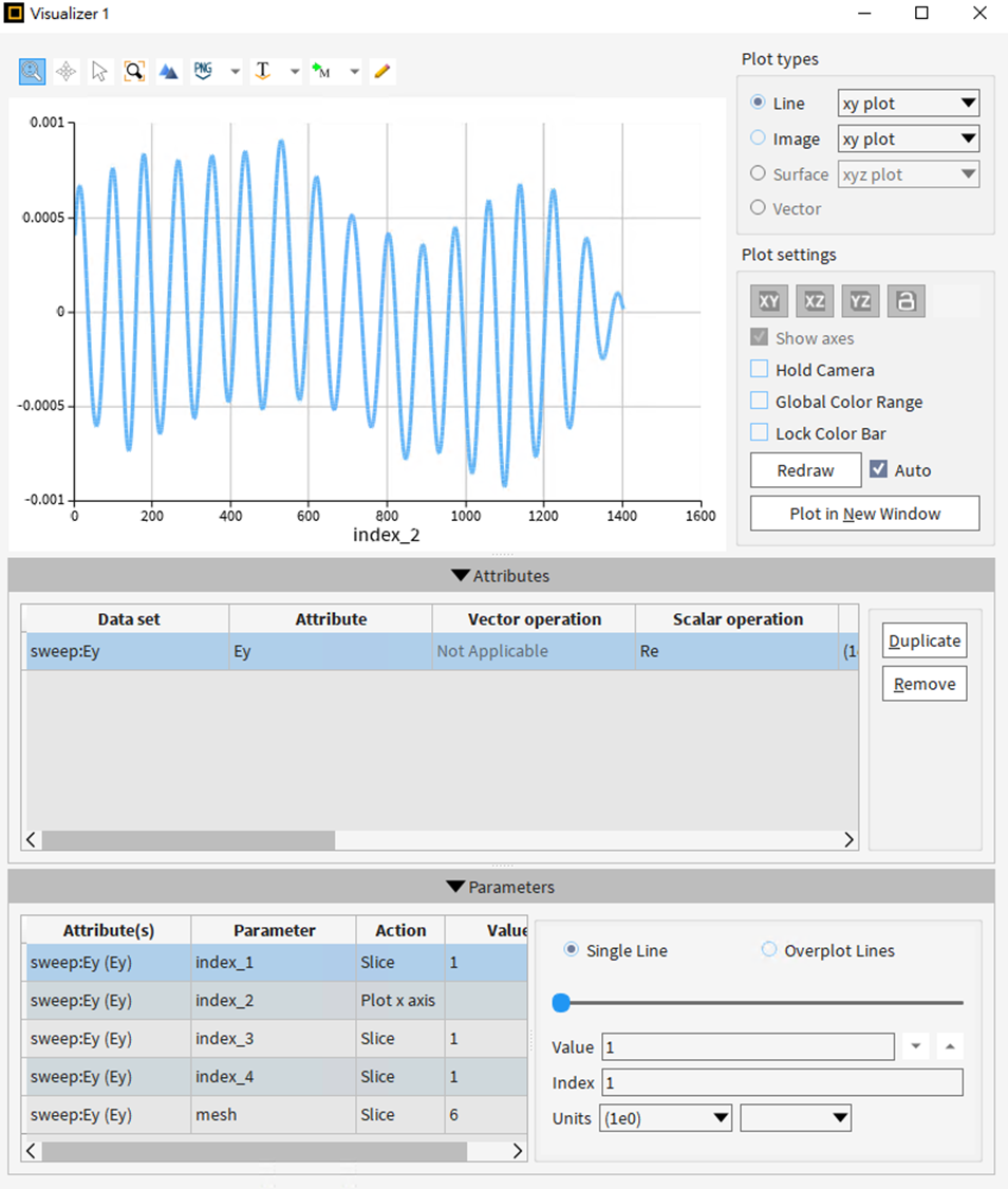
I also tried to capture the Ey here:
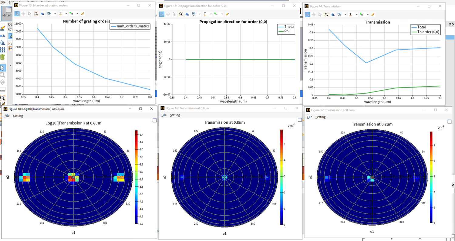
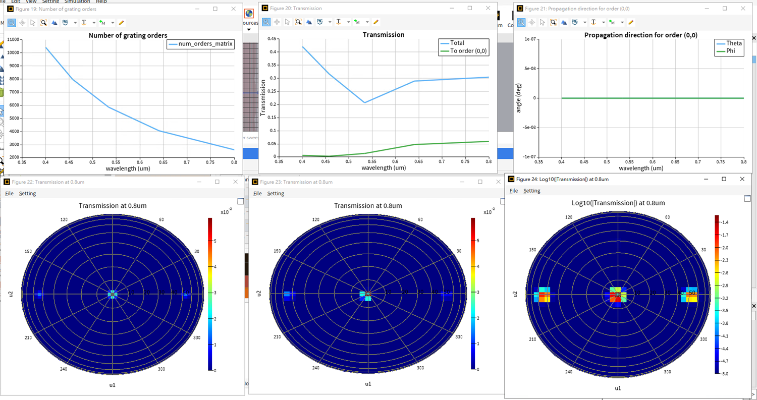
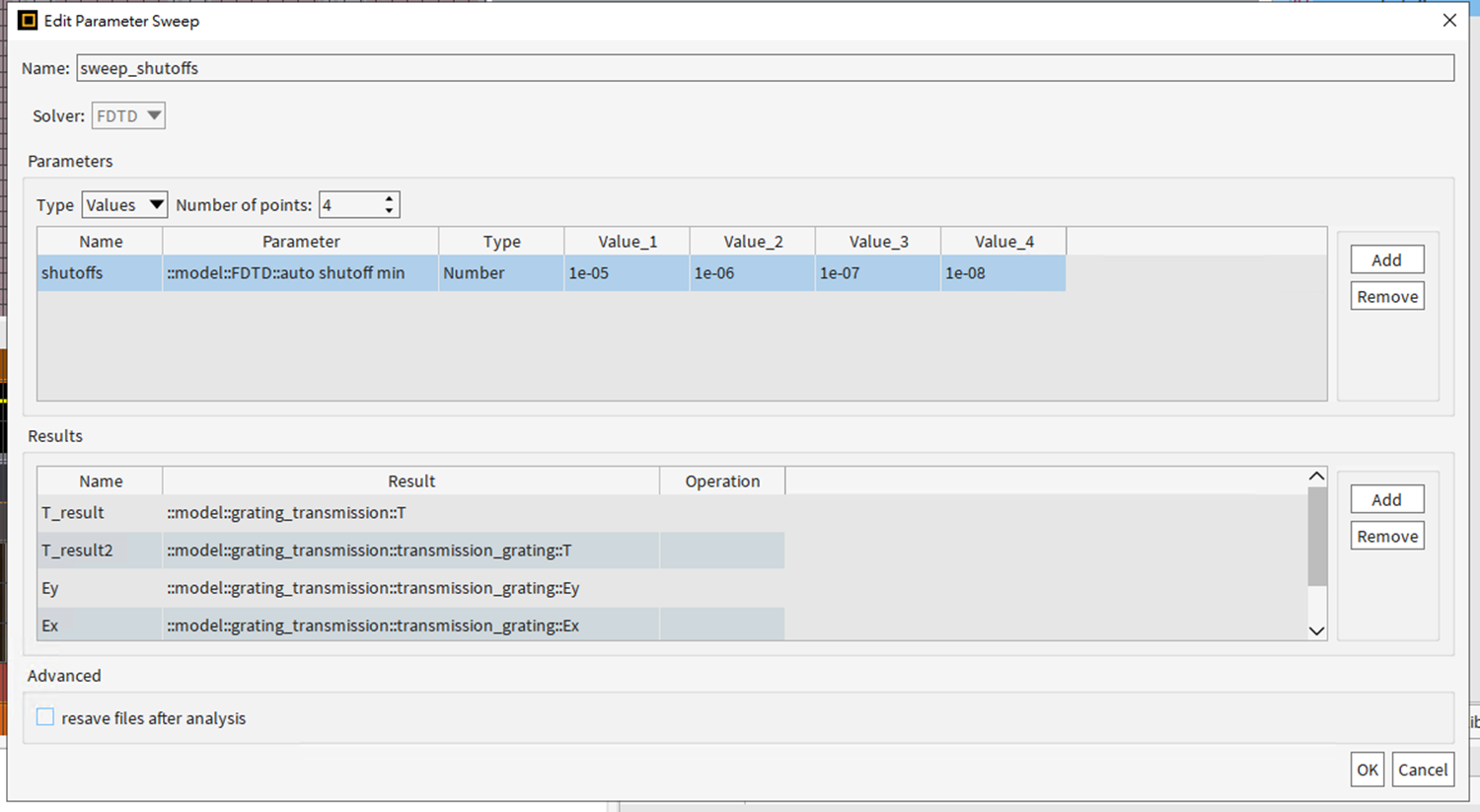
Furthermore, I ran simulations using a broadband spectrum (0.4 to 0.8 micrometers) with different auto shutoff levels: 1e-05, 1e-06, 1e-07, and 1e-08.
Below are the results of those simulations:
- Auto shutoff 1e-05:
2. Auto shutoff 1e-06:
3. Auto shutoff 1e-07:
4. Auto shutoff 1e-08:
The number of gratings, transmission, and propagation orders are almost the same for the results from different mesh cells per wavelength.
For the broadband spectrum, I am assuming that the distribution of the light source's spectrum is normal, based on Guilin Sun's explanation provided in the Ansys Forum.
I also obtained the results for T and Ey from the sweep.
For mesh cells per wavelength, the results are the same from mesh 6 to 18.
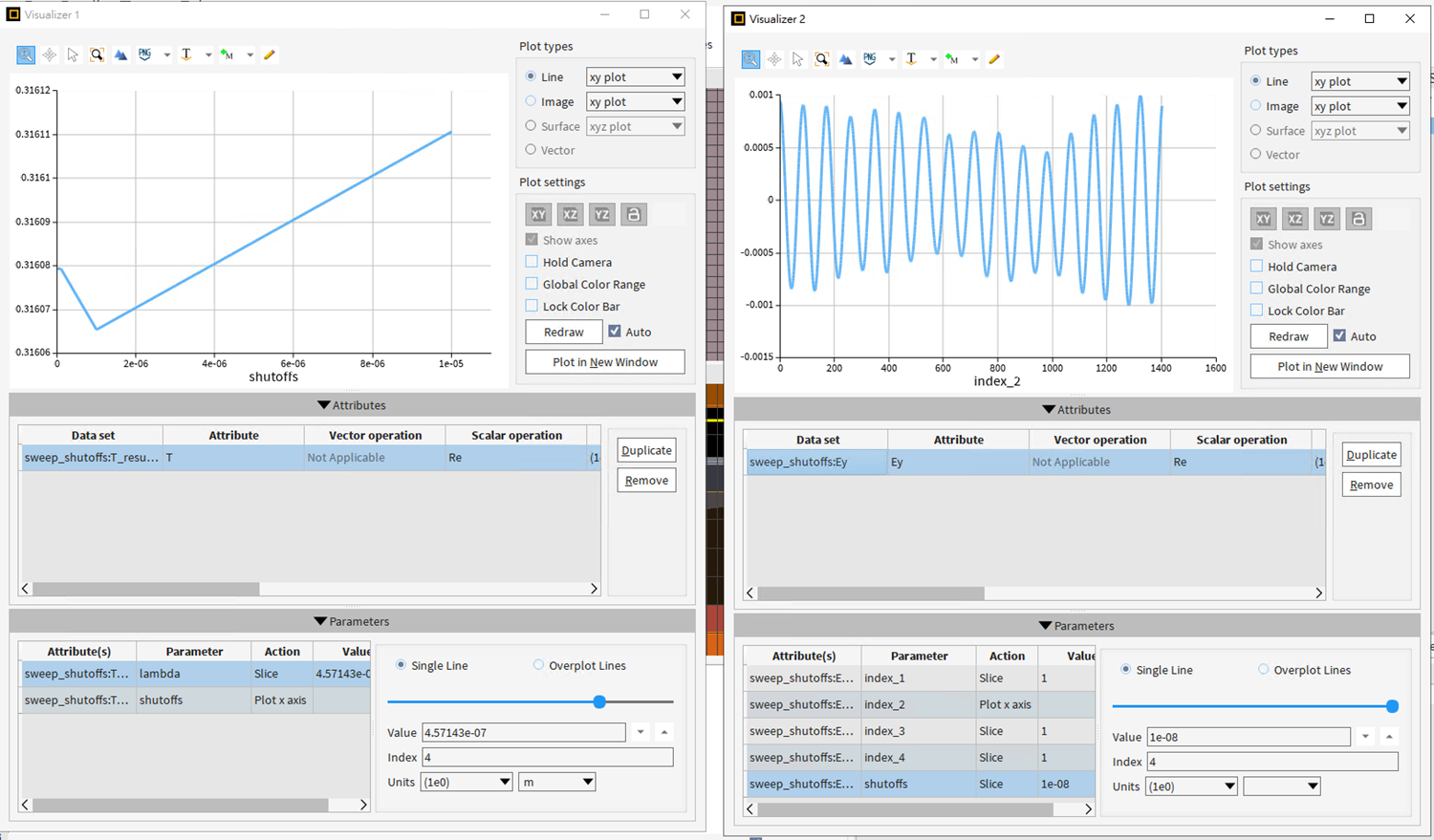
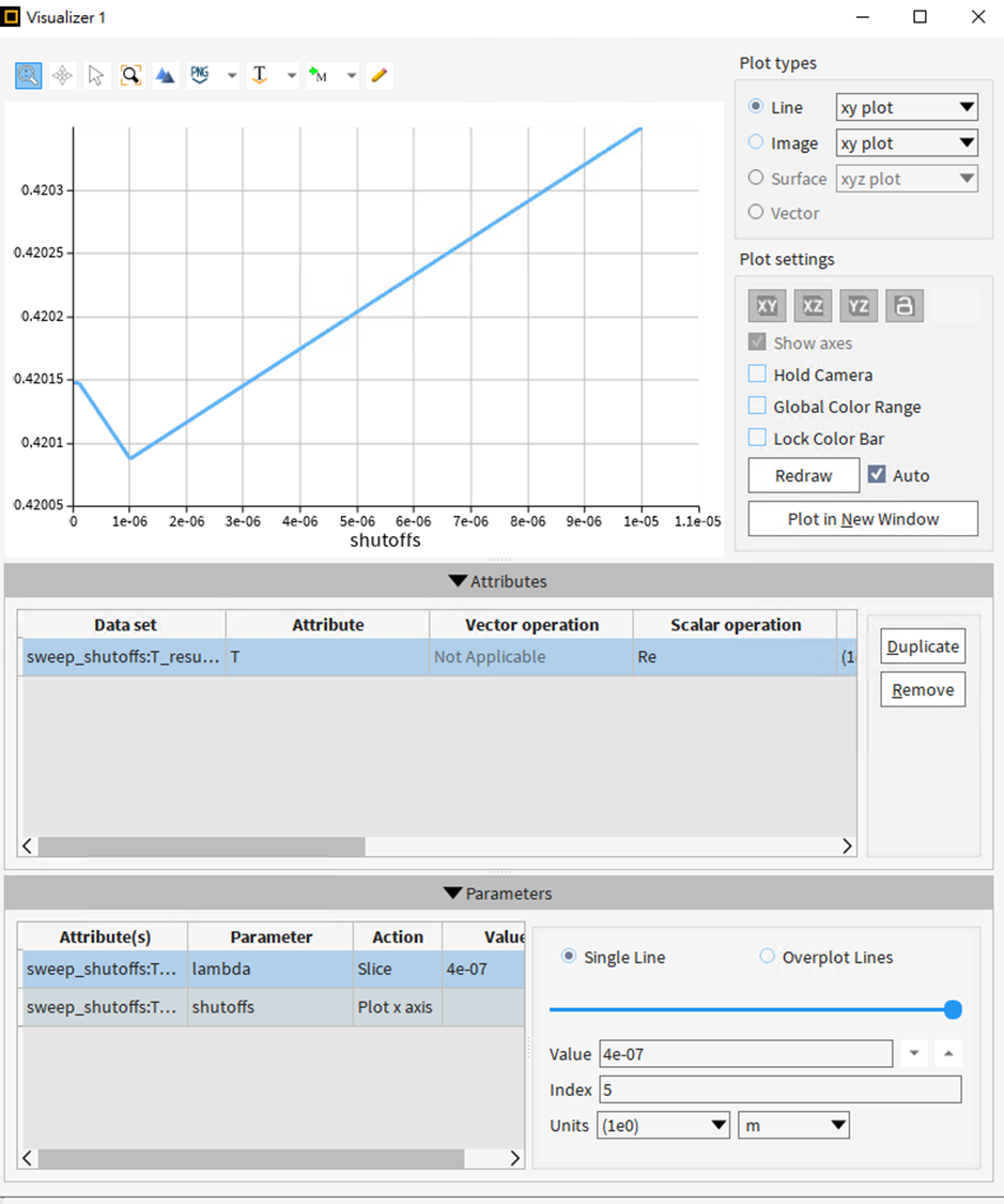
For the auto shutoff settings from 1e-05 to 1e-08, the results are slightly different for each parameter, as shown below:
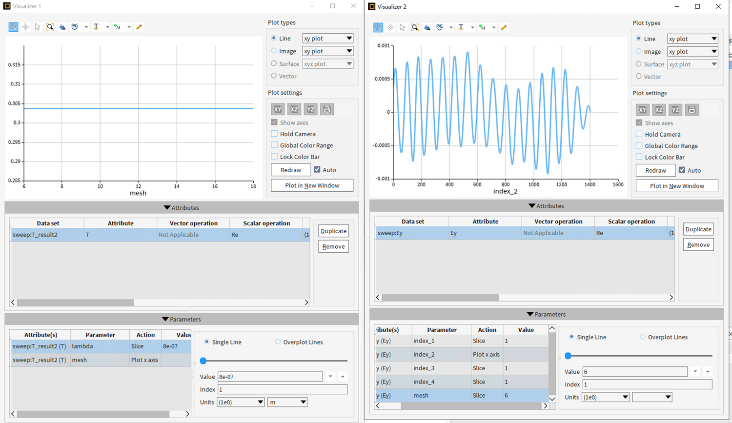
a. T (lambda: 8e-07) and Ey (shutoff: 1e-05)
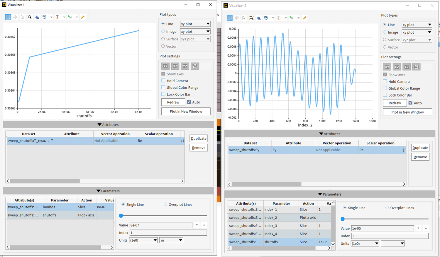
b. T (lambda: 6.4e-07) and Ey (shutoff: 1e-06)
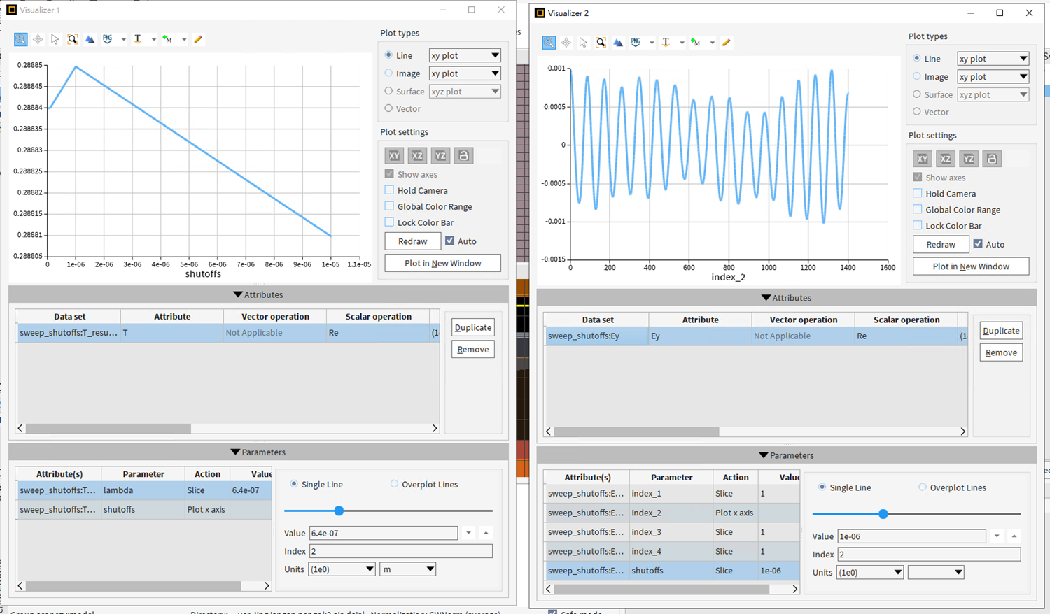
c. T (lambda: 5.33e-07) and Ey (shutoff: 1e-07)
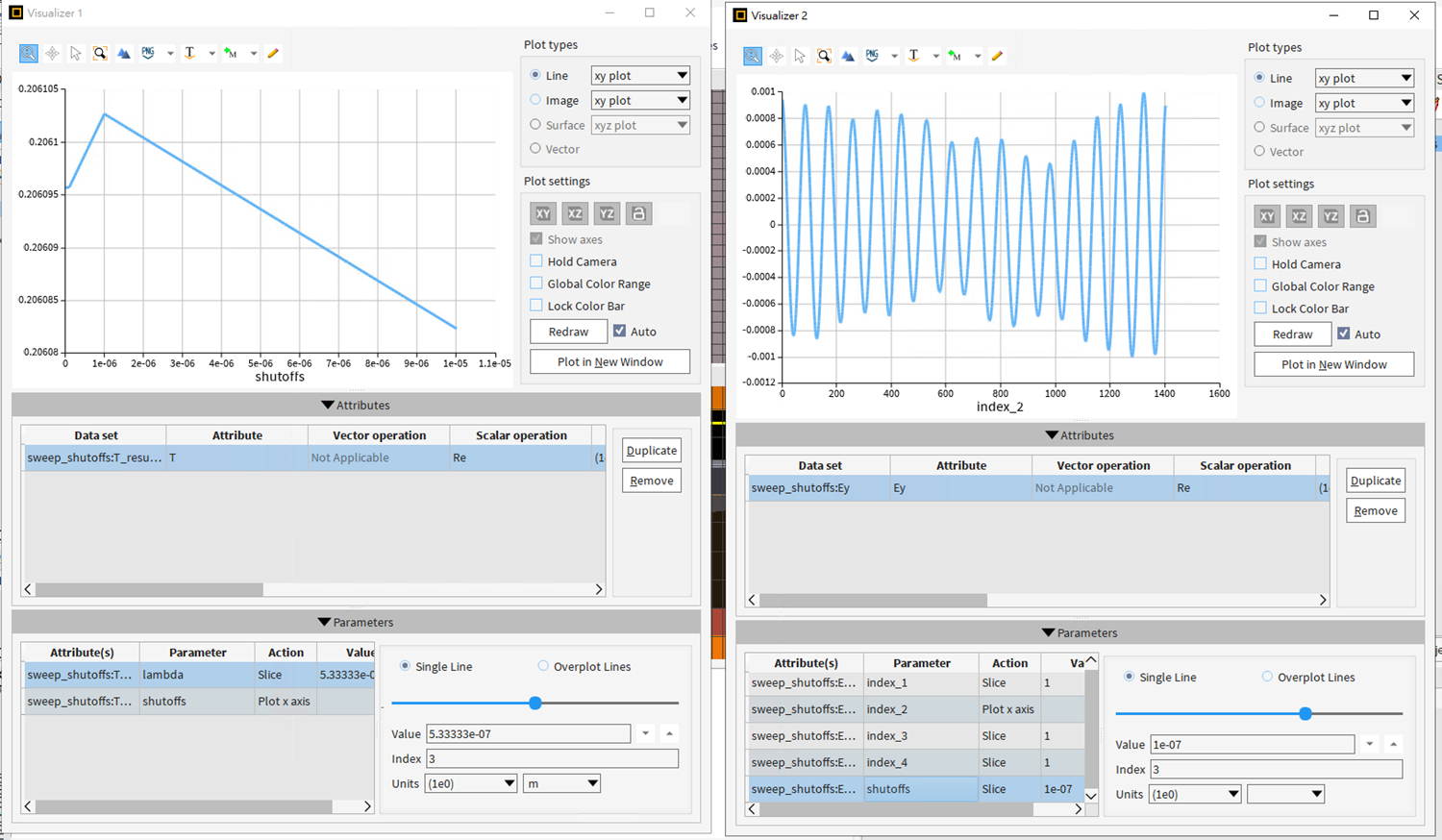
d. T (lambda: 4.571e-07) and Ey (shutoff: 1e-08)
e. Lambda 4e-07
The results for T sometimes decrease and sometimes increase. Is this normal?
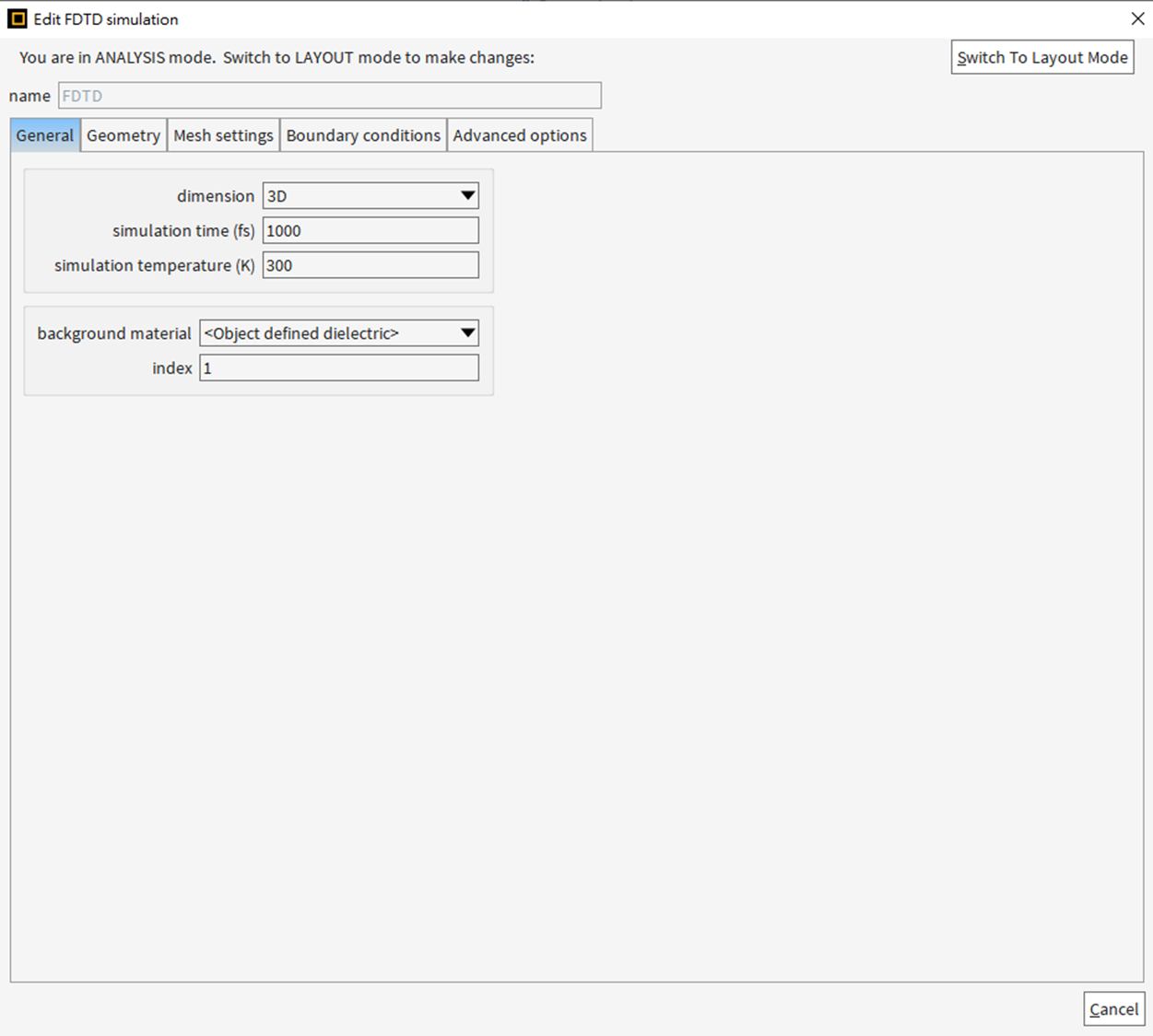
Regarding the Ey, some oscillations are present, but can we assume they indicate very high or poor results? (The simulation time was 1000fs, which is the default.)
From these results, does my simulation seem convergent enough to you? Or is there anything concerning about the results or my settings?
Best regards,
Miller.
-
- The topic ‘Question regarding the auto shut off in FDTD simulation.’ is closed to new replies.


-
4678
-
1565
-
1386
-
1241
-
1021

© 2025 Copyright ANSYS, Inc. All rights reserved.

