-
-
July 22, 2021 at 9:53 am
Mansoureh
SubscriberHi,
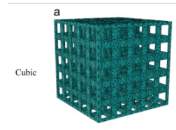
I want to model this structure fr the compression test
July 22, 2021 at 2:05 pmRam Gopisetti
Ansys Employeeyou can model the unit lattice using the Material designer included in ANSYS WB and set the repeat count to desired value.
 then you can proceed to save the geometry as .scdoc file from material designer and you can import the saved CAD into workbench as follows
 based on the your definition of having those D1,D2,D3,D4 and D5 are called as JC-Damage constants these are used for predicting the erosion on ground terms "Breakage". Well you also need to have elastic and JC-plasticity parameter as follows
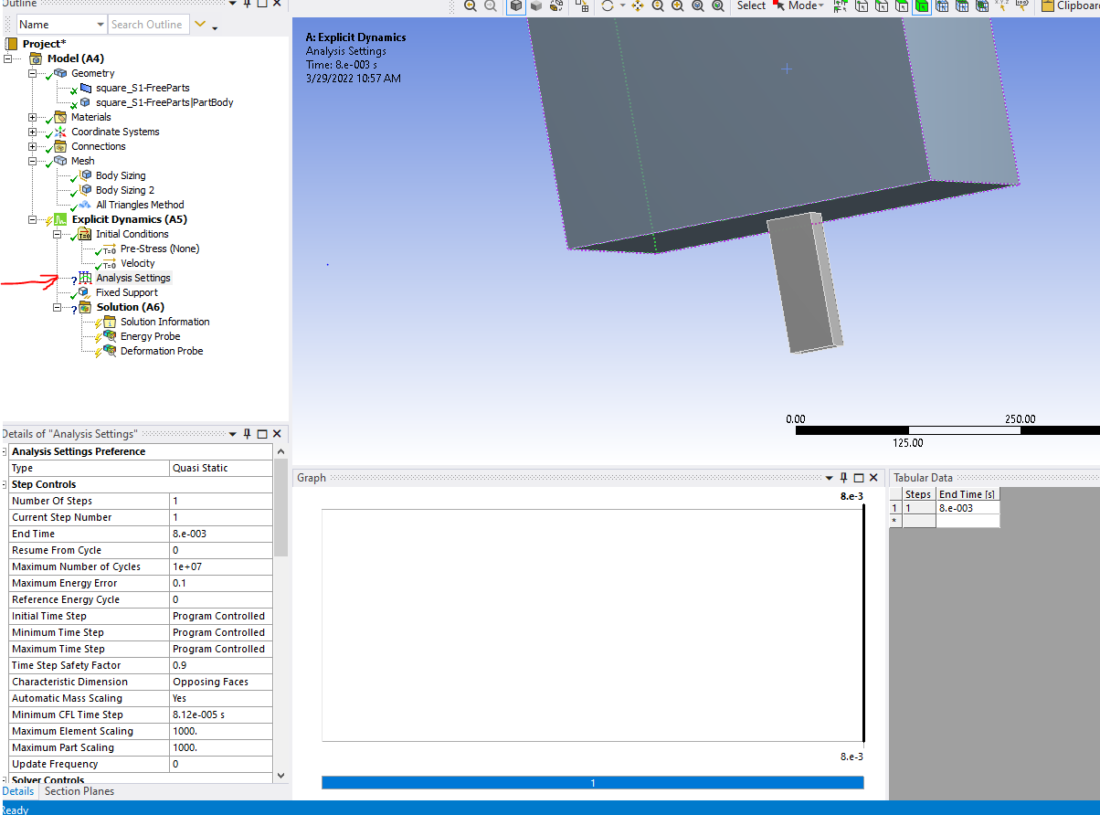
 you can do QUSI STATIC by changing the type in Analysis settings as follows. Moreover, you need to know the minimum CFL time to proceed further.

to make sure your structure follows the material failure law make sure you enable the following option.
 you can use the RAM HEAD like geometry and apply a displacement vs time cure to apply the compression load at given strain rate.
Comment down your results for further help.
Cheers, Ram
-
January 20, 2023 at 7:15 am
Riccardo Petrelli
SubscriberI need your help,please
July 25, 2021 at 6:01 amMansoureh
SubscriberDear ram_gopisetti
Hello and Thank you very much for answer the question. I have another question and I am in doubt about them, sorry if they are very basic and simple.
1.Should I find the minimum CFL time by doing modal analysis?
2.And if we want to use Quasi-static analysis, do we have to find CFL always and for any type of structure should I do the modal analysis?
3.If I want to use Autodyn, do I need to know CFL time as well?
4.and final question is about the time of analysis is quasi-static. this displacement that I mentioned in the first question is around 1.8 mm/min in 5 minutes. I think it should take a lots of time to solve due to the type of quasi-static and the time, maybe several days? am I right?
5.and how can I apply this displacement in 5 min? should I increase the number of steps? how many?
Thank you again for your help.
-
January 17, 2023 at 10:16 am
Riccardo Petrelli
SubscriberPlease i have a similar problem for my tesis work, help me? Pkease
July 26, 2021 at 1:43 pmMansoureh
SubscriberDear ram_gopisett
May I ask you to do a favor for me? to guide me step by step to solve my problem, I want to be sure that I am going it correctly.
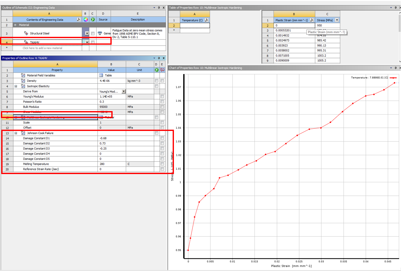
2.At first, I defined my material. I extract the true stress and true strain from tensile test data. and add them as a Multilinear Isotropic Hardening.
I read that, If we want to use LS-Dyna for simulation and use Johnson cook failure criteria, we have to use the plasticity and failure criteria the same. I mean both of them should be based on Johnson cook. Is it true? Because here I used Multilinear Isotropic Hardening and Johnson cook failure as the below image :
I have a question about "Reference Strain Rate", should I use ZERO? because I have just three damage constant. and melting temperature is important?

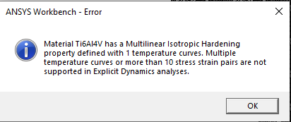
2.But here before starting to do anything ansys gives me an error that:

If I clean 22 from temperature, it shows me this error again. I searched for this error but I could not find anything to how can I solve it. Please guide me.
3.I import my geometry and meshed it. In both mesh and body size, I added "0.003 mm" as the size of elements; and meshed it. should I use this size to calculate CFL?
4.the main problem for me is related to Analysis settings. Can you help me to fill it?
I found CFL from a video in Ansys youtube and it is defined by the below equation

I calculated my CFL time and it is equal to 5.31e-7. I should mention it I consider f=1 in the above equation. is it true?
Can you guid me about :
Number of steps?
Initial, minimum and maximum time steps?
End time ?
Static Dampin ?
Thank you. dear @ram_gopisett.
July 27, 2021 at 3:24 pmRam Gopisetti
Ansys Employee
yes, your CFL is correct. and it is influenced by the mesh size.
reference strain rate is the strain rate in your experiment which is used to find the EPS vs Stress. and check your material definition, only use the plastic terms and your elastic terms comes from isotopic elastic terms. Use only 5-8 points in the material definition.
check the following links for futher help
cheers, Ram
March 29, 2022 at 5:45 amPratikansys
SubscriberAfter changing the CFL time there is no green tick sign appearing in analysis settings I want to crush a square aluminium pipe quasi-statically. I have done compression test in UTM at loading rate of 10mm/min. I want to simulate this by using Quasi static setting available in Ansys Explicit. I have applied 10mm/min velocity to 600 Kg steel mass that is compressing aluminium pipe below it. Please help me.

January 20, 2023 at 7:12 amRiccardo Petrelli
Subscriberwere you able to simulate it? I should have had some questions for youFebruary 8, 2023 at 6:08 pmPatrick Straker
Subscriberwhy i have to calculate the CFL manuly arent all relevant numbers already statet in the Material definition and Mesh Metric ? or is there a thing i do not see ?
Viewing 7 reply threads- The topic ‘quasi static compression test’ is closed to new replies.
Innovation SpaceTrending discussionsTop Contributors-
5094
-
1831
-
1387
-
1248
-
1021
Top Rated Tags© 2026 Copyright ANSYS, Inc. All rights reserved.
Ansys does not support the usage of unauthorized Ansys software. Please visit www.ansys.com to obtain an official distribution.
-
The Ansys Learning Forum is a public forum. You are prohibited from providing (i) information that is confidential to You, your employer, or any third party, (ii) Personal Data or individually identifiable health information, (iii) any information that is U.S. Government Classified, Controlled Unclassified Information, International Traffic in Arms Regulators (ITAR) or Export Administration Regulators (EAR) controlled or otherwise have been determined by the United States Government or by a foreign government to require protection against unauthorized disclosure for reasons of national security, or (iv) topics or information restricted by the People's Republic of China data protection and privacy laws.


