TAGGED: ansys-q3d-extractor, q3d, q3d-extractor, skin-effect
-
-
December 5, 2023 at 4:30 pm
Jan Stoebe
SubscriberHi,
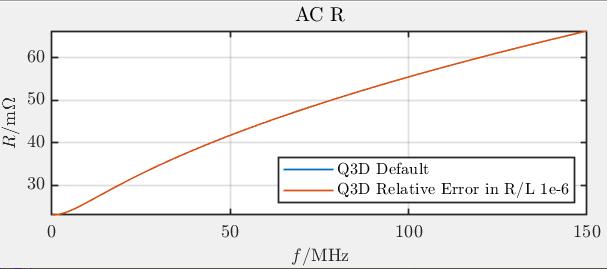
I tried the beta option Enhanced Accuracy in DC-to-AC Transition Region in Q3D Ectractor in Ansys AEDT 2023R1. My test case consists of a single straight rectangular conductor of width w = 150 um, thickness t = 25 um, length l = 5 mm made of copper in vacuum. I simulated from DC up to 150 MHz (= solution frequency), where the skin depth is 5.4 um. I could not see any change/improvement, by tightening the Relative Error in R/L from default to smaller values. I also did not see any additional frequencies being solved.
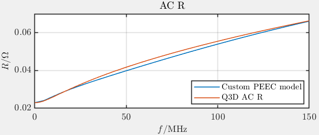
I have my own matlab script for this testcase, which uses partial inductances (i.e. PEEC method) to calculate the AC R at discrete frequency points. I see very precise agreement for the AC R value (150 MHz Solution Frequency) and the DC R. The transition range is also quite close, but I wanted to see if I can increse the accuracy further.
So does the beta feature work correctly and there is no change to be expected, when tightening the transistion for this testcase? That seems odd to me. Thx in advance.
-
December 6, 2023 at 3:01 pm
Praneeth
Ansys EmployeeHi Jan,
Please see if you are setting up the simulation as per the requirements by going through the "Transition Region RL Analysis (Beta)" section in the Q3D Help document available under the Help menu.
Best regards,
Praneeth.
-
- The topic ‘Q3D RL Analysis Enhanced Accuracy in DC-to-AC Transition Region’ is closed to new replies.


-
5039
-
1749
-
1387
-
1248
-
1021

© 2026 Copyright ANSYS, Inc. All rights reserved.


