TAGGED: fom, optimization, python
-
-
October 31, 2024 at 3:21 pm
hammam.albustami
SubscriberHello,
I'm trying to write a code that optimize groove depth and duty cycle as a function of field ampltides for periodic grating structure. How to add a Figure of merit script in python that update the lumerical ? is there something that could be help me (like structure group) to update figure of merit in lumerical using python script ?
Thanks -
November 1, 2024 at 5:31 am
anna.wirth-singh
Ansys EmployeeHello,
There are currently two types of FoM supported by lumopt - one is a mode monitor, and the other is a Field Region monitor. Is your grating structure coupling into a waveguide? If so, it would probably be easiest to use the mode type FoM to optimize the efficiency of your grating. This example is a good starting point for that:
Inverse Design of Grating Coupler (2D) – Ansys Optics
Inverse design of grating coupler (3D) – Ansys Optics
It is probably most straightforward to start with one of these examples and try to adapt it to your application if possible. This waveguide crossing example is also helpful: Inverse design of waveguide crossing – Ansys Optics
If you are not using your grating to couple into a waveguide, then you might be able to use the more general Field Region FoM. Here is an example using that one: Inverse Design of Metasurface Color Router – Ansys Optics
I hope these resources will get you started; please feel free to reply back if you have further questions.
Best,
Anna
-
November 4, 2024 at 6:27 am
hammam.albustami
SubscriberThanks Anna for replying me,
My grating structure is simple Silicon rectanular periodic structure used for subwavelength dielectric laser accelaration purposes.
so, my optimization is to increase the field amplitude of evanescent in first grating order.
-
November 4, 2024 at 6:30 am
hammam.albustami
SubscriberIts important to say that I'm using RCWA simulation
-
November 5, 2024 at 2:27 pm
anna.wirth-singh
Ansys EmployeeHi, Thanks for clarifying - I apologize, I initially thought you were using lumopt for a more complicated structure. To optimize a simple strucutre it would be much more straightforward to use the built-in optimization and sweep utilities. Please see these pages if you have not already:
Optimization utility – Ansys Optics
Creating optimization tasks using a script – Ansys Optics
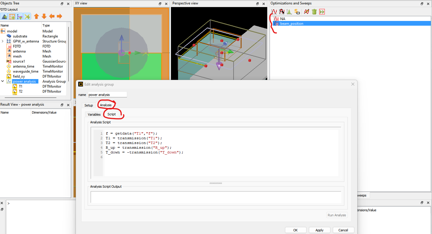
I think that defining an Analysis group would be the best way to define a custom figure of merit, so it sounds like you are on the right track. In the Analysis group script, you can perform calculations and if you specify those variable to be results, then they can be used as FoM for optimization.
While this example is not for RCWA, this example has both an analysis group and an optimization that uses the result from that analysis so it will be useful to have a look:
Plasmonic gap waveguide – Ansys Optics
Specifically, 'T1' here is later set as the FOM for optimization. This script is very simple but a more complex script could be used instead.
I hope this is helpful; feel free to reply back with follow-up questions.
Best,
Anna
-
- You must be logged in to reply to this topic.


-
4718
-
1565
-
1386
-
1242
-
1021

© 2026 Copyright ANSYS, Inc. All rights reserved.


