-
-
September 1, 2021 at 2:39 pm
Swoopoo
SubscriberHello,
I have imported my HFSS model into circuits and can replicate the S11 parameter there with no issues. After impedance matching with the smith tool and confirming the desired result in circuits I push the excitation to HFSS. After reanalyzing HFSS with the pushed excitation (Yes - under edit sources the excitation has changed) the S11 parameter didn't change and the model is not matched.
Does anyone know a solution to this problem?
September 2, 2021 at 6:23 amPraneeth
Forum Moderator
Pushing the excitations from circuit to HFSS is sufficient for the cosimulation. This is called the dynamic link and it takes effect immediately.
You do not need to simulate again for this. This can be confirmed by looking at the excitations like you have mentioned.
For comparison of the results before and after cosimulation, it is advised to copy and paste the S parameters before performing cosimulation.
Please go through this video course - Cosimulation Using Ansys HFSS - ANSYS Innovation Courses for better understanding of the cosimulation concept and see if you can achieve the required matching.
All the very best.
September 2, 2021 at 6:34 amSwoopoo
SubscriberHello unfortunately that is not the case. I followed multiple courses and guides on the dynamic link feature in ANSYS HFSS. But in contrast to their solution mine looks like this:
This is the circuit simulation. As one can see the unmatched red curve and the green curve after applying the matching network. The circuit simulation displays the desired result and confirms the matching should work.
Now the same plot before and after pushing excitations in HFSS:
The red (before) and green (after) curves overlap because the matching network excitation was NOT applied to HFSS even tho the software says the excitation push was successful. I'm really confused since the matching apparently worked, according to ANSYS Circuits.
The Model is a DrivenModal Solution (tried with Terminal Solution as well - same result) with one lumped port as excitation.
I'm at my wits end to be honest.
BR
Swoopoo
September 2, 2021 at 10:32 amPraneeth
Forum Moderator
Please share the schematic of your circuit to help us serve you better.
Best regards.
September 2, 2021 at 12:29 pmSwoopoo
Subscriber
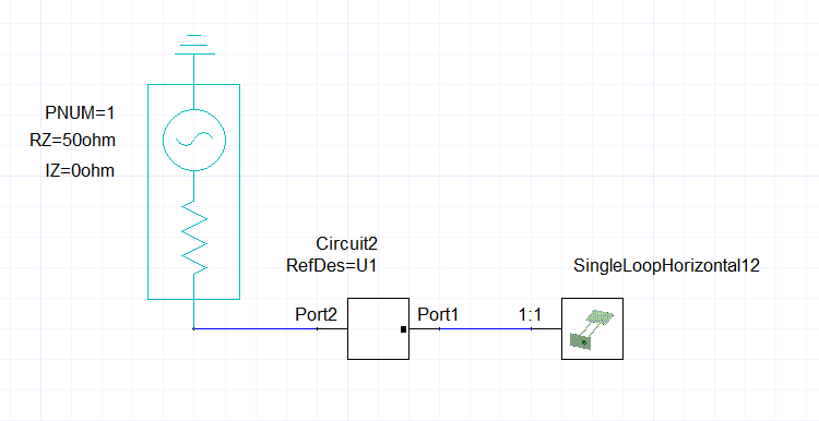
The Source is a Microwavegenerator with 28V at 2.87GHz. The Load is a wire loop with a lumped port as an excitation.
I need to match the 50 Ohm impedance from the source to the impedance of the load. There are two workflows I found - one stemming from the ANSYS video and one from the internet.
ANSYS workflow:
Impedance match from the smith chart center (50 Ohm) to the complex conjugate of the impedance of the source. This is the way I'd imagine it being correct, since this applies 50 Ohms at Port 1 and the to be matched impedance at Port 2 (Load side).
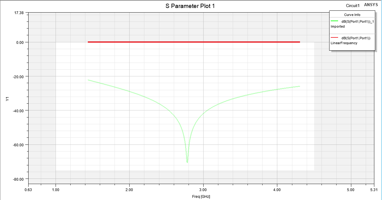
An alternative I found on the internet - which produces amazing results according to ANSYS (see first image in my post above) is to start at the impedance of the load and match it to 50 Ohm and than inverting the direction of current flow through the matching network.
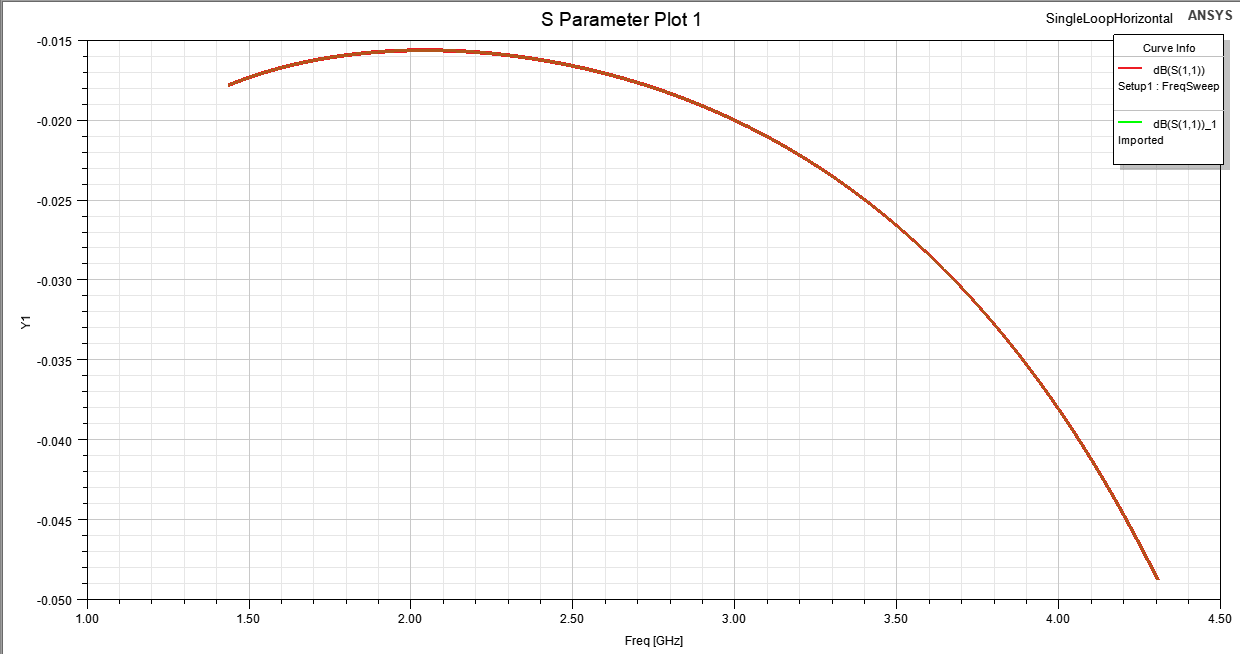
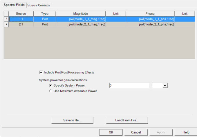
Independent of what workflow I follow, I can't manage to get the desired effect in HFSS. The model behaves unchanged after pushing the excitations.
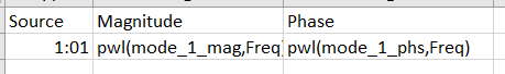
Do I need to use a special port for the matching network influence to take effect?
September 7, 2021 at 9:06 pmDan Dv
Ansys EmployeeNote that the dynamic link will not change the s-parameter results inside of HFSS. Pushed excitations only change the results that depend on those excitations, such as field plots. The combined s-parameters of the dynamic link between the Circuit tool and HFSS can only be seen through preforming an LNA in Circuit and plotting the s-parameters in Circuit.
February 8, 2023 at 12:59 pmbyron.montgomery
SubscriberI'm having the same issue, no matter what I do "Push Excitations..." only looks like it's replotting all the far fields. Even after putting some amplifiers in line I still can't get the far fields to reflect the new excitations.
April 12, 2023 at 5:20 pmJoe O'Reilly
SubscriberPush Excitations is not working for me. HFSS 3d plots are not being updated even though status bar says the push was successful. Has this issue been resolved?
April 13, 2023 at 1:11 pmDan Dv
Ansys EmployeeJoe O'Reilly, which plots are not getting updated? Note that pushed excitations will not change the s-parameter plots in HFSS. Only field plots provided you plot based on the pwl excitations that got pushed from the Circuit tool.Â
The only way to see the combined s-parameters is in the Circuit resutls.Â
April 13, 2023 at 4:10 pmJoe O'Reilly
SubscriberDan. I am looking at far field plots at 6.5GHz in HFSS. The circuit file source is microwave set to 1V AC and 6.5GHz. Still not updating HFSS. Is there any way I could send you my file to see if I am doing something wrong?
April 13, 2023 at 4:37 pmDan Dv
Ansys EmployeeHi Joe. Unfortuantely no, we cannot look at project files sent through this forum. If you are a full commerical customer, you can create a Service Request throught the customer portal. Or if you are with a Channel Partner, they should be able to provide direct support.Â
A couple of things to check. If you right mouse click on the Excitations icon and choose edit soruces, make sure that the magnidue/phase properties are pwl based indicating they are getting info from the Circuit solve.ÂÂ
I'd also try making some kind of radical change to the circuit just to double check if the fields are changing or not.Â
April 13, 2023 at 4:53 pmApril 13, 2023 at 4:56 pmDan Dv
Ansys EmployeeHi Joe. That does look correct from here. Are you a direct or Partner based Ansys customer?Â
Â
April 13, 2023 at 4:58 pmJoe O'Reilly
SubscriberDan. Good question. How would I find that out?
April 13, 2023 at 5:03 pmDan Dv
Ansys EmployeeThe first order question, do you have the full version of software, or the student version? If you are a corporate customer with the full version, does you company but directly from Ansys or through one of our Channel Partners? You may have to check in with your IT department to verify that.Â
April 13, 2023 at 5:04 pmJoe O'Reilly
SubscriberFull version. I am pretty sure we bought directly from Ansys.
April 13, 2023 at 7:42 pmDan Dv
Ansys EmployeeHi Joe. Yes, in that case you should be able to open a Service Request on the Ansys Customer Portal.
If you have trouble logging in, there is more information about how to do that on this page:
https://webapps.ansys.com/era/ssosupport/customerportalhelp
Please put in a SR ticket and myself or one of my colleagues will be able to assist further. Once the ticket is in the system you will be able to share the project with us.ÂApril 13, 2023 at 11:01 pmApril 14, 2023 at 1:35 pmApril 14, 2023 at 2:45 pmApril 14, 2023 at 4:53 pmDan Dv
Ansys EmployeeHi Joe. Hmm, that might imply that your support is handled by one of our Channel Partners. This forum does not give me enough info to access your account details. But if you send email to ansys-community-help@ansys.com and aks if you are a direct customer or a Channel Partner account they will be able to look you up and help you obtain support.Â
Viewing 20 reply threads- The topic ‘Push Excitations not working in dynamic link’ is closed to new replies.
Ansys Innovation SpaceTrending discussions- HFSS Incident Plane Wave excitement mode
- Ansys Maxwell 3D – eddy current
- Simulation of capacitor combining eddy currents with displacement currents
- dq graph non-conformity
- Simplorer+Maxwell Cosimulation results and Maxwell results mismatch
- Parametrizing coil “terminals” with coil geometry
- Maxwell circuit – PWM
- Plotting Ex, Ey and Ez in vector forms individually
- Ansys-MATLAB Co-Simulation
- Calculating E-field tangential to a 2D resonant structure on a sapphire chip
Top Contributors-
1932
-
823
-
599
-
591
-
366
Top Rated Tags© 2025 Copyright ANSYS, Inc. All rights reserved.
Ansys does not support the usage of unauthorized Ansys software. Please visit www.ansys.com to obtain an official distribution.
-