TAGGED: bend, Lumerical-EME, waveguide
-
-
August 1, 2024 at 8:04 pm
andeloth
SubscriberHi,
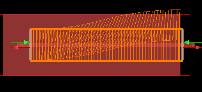
I noticed that while I was running EME simulations with bent waveguide mode settings for the cells, I noticed that there was a second set of cells shown in the GUI that follow the "bend" of the waveguide. Since I am using EME, I'm actually using a straight waveguide and just defining bent mode settings.
Is there a purpose to the graphics that show the bent waveguide cells other than a visual indicator that that is where the waveguide would go if this was an FDTD simulation, for example?
-
August 2, 2024 at 5:36 pm
Guilin Sun
Ansys Employeeyes, this is the feature many users dreamed of.
-
Viewing 1 reply thread
- You must be logged in to reply to this topic.
Innovation Space


Trending discussions


Top Contributors


-
4618
-
1530
-
1386
-
1210
-
1021
Top Rated Tags


© 2025 Copyright ANSYS, Inc. All rights reserved.
Ansys does not support the usage of unauthorized Ansys software. Please visit www.ansys.com to obtain an official distribution.


