TAGGED: designmodulator, FDE, losses, metal
-
-
July 27, 2023 at 1:04 pm
sb5e21
SubscriberHello,
As per the title, I conducted a simulation of Nb2O5 on SiO2 with Au electrodes positioned as illustrated in the picture (FDE, PML BCs). The aim was to study the loss behavior by varying the gap between the electrodes. I obtained results for both TE and TM modes, revealing that the TM mode exhibits higher loss than the TE mode. However, this seems counterintuitive to me since I expected the TE mode to have higher loss due to oscillation in the direction of the electrode. Could someone kindly assist me in clarifying these results?
Thank you
-
July 31, 2023 at 10:56 pm
Guilin Sun
Ansys EmployeeThis can be a tough question.
1st, please check if your TE and TM definitions are the same as Lumerical.
2nd, please try to increase the PML distances with fixed mesh size, not fixed mesh points.
3rd, the loss mechanism might be different from weak waveguides where there is sime simplifications. Or the PML loss might be also a factor. You may try to plot E intensity in log scale and check in what case the E fields exists the most inside the metal.
This might be a more theoretical question other than simulation. Maybe this can revise the existing theory. Of course you will need to be cautious and dig more in details.
Â
-
- The topic ‘
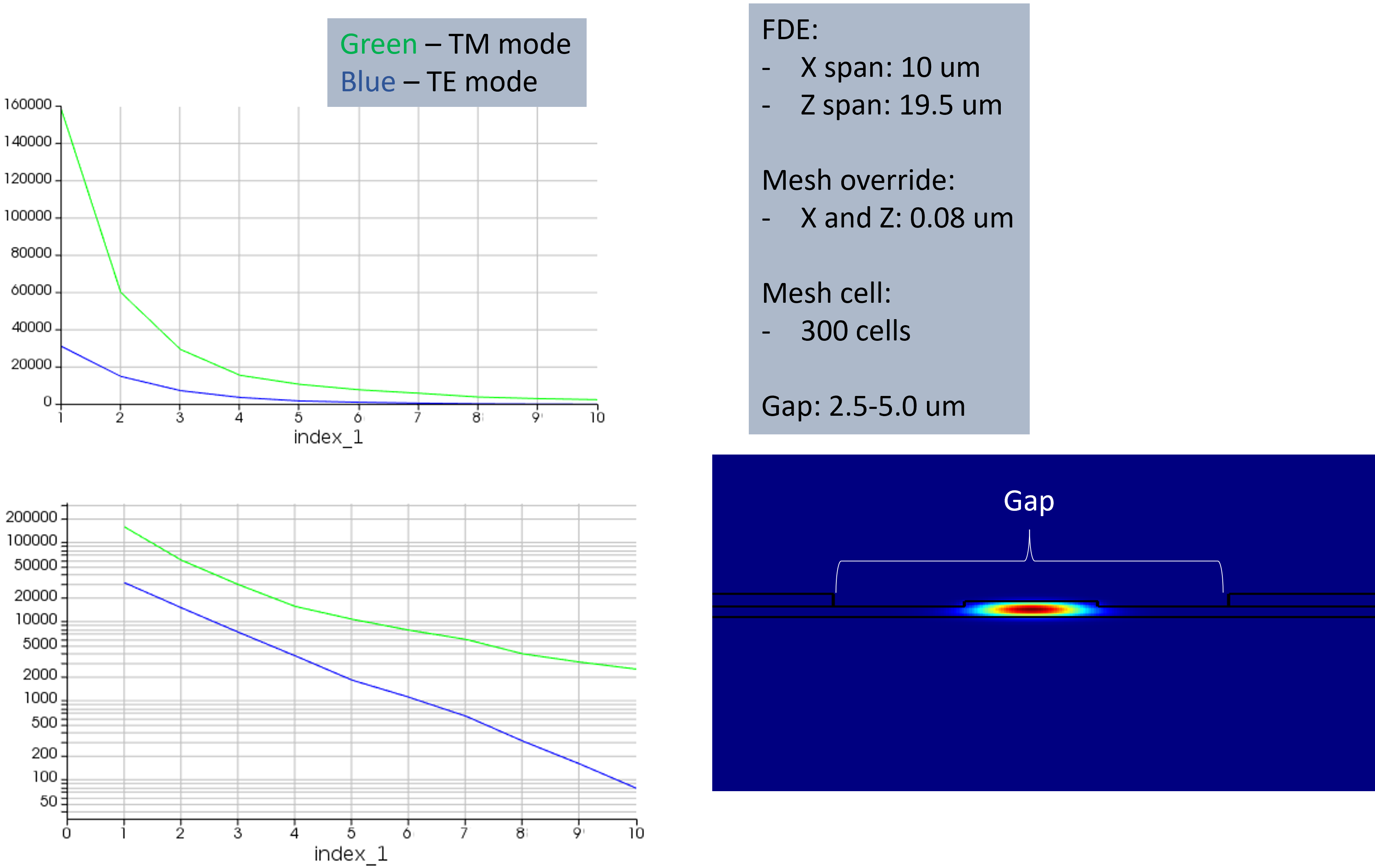
Propagation Loss from metal electrodes’ is closed to new replies.
-
2878
-
970
-
852
-
599
-
591
© 2025 Copyright ANSYS, Inc. All rights reserved.