TAGGED: biomechanics, biomedical, poor-quality-elements
-
-
March 17, 2024 at 7:07 pm
javat33489
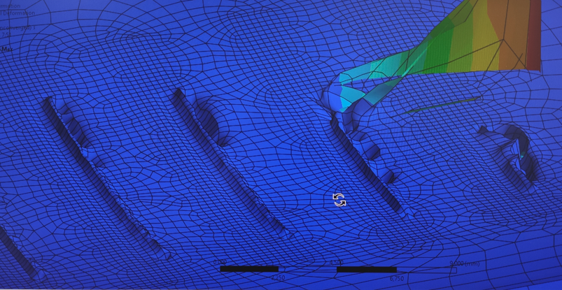
SubscriberHi all. I'm calculating a die with teeth. I use two steps. In the first step I press the die into the surface, in the second step I add a side load to move the pressed die. Both splints are made of steel. I use bilinear isotropic hardening. In both cases I use the applied force. I use symmetry along the movement of the die, everything should work. The die is as close to the surface as possible. The mesh is structural and quite fine (0.1 mm on the tooth and surface). The total mesh is 900k elements, the problem is solved within 20 hours. I use large deformations.The problem is that at the end of the first step the mesh begins to behave inappropriately; it begins to show sharp corners, violating its integrity. At the end of the day I have a distorted error.Picture of the depressed surface from the tooth:I also tried different types of contacts, used the detection radius (on/off), I tried touch control - without it the problem cannot be solved at all. I also tried using two contacts at once: one with Gaussian points, the second nodal normal that target, this also does not work. Why is this happening? -
March 21, 2024 at 2:01 am
javat33489
SubscriberHelp please
-
March 21, 2024 at 5:31 am
mjmiddle
Ansys EmployeeFor a static analysis, make sure the bodies are touching in the beginning. If you have set it up with intersecting geometry for a press-fit, make sure the first element on the surace is larger than the interference. You can make one inflation layer to make sure the first layer of elements is larger than the interference.
Try the model without symmetry to see if that is causing a problem. Lowering contact normal stiffness can help with convergence. Try a normal stiffness of 0.1 or 0.01 if that doesn't help. Set the "Update stiffness" to "each iteration" or "each iteration, aggressive." For nonlinear contacts, setting "interace treatment" to "adjust to touch" helps with convergence. A displacement load in place of a force load can be much more stable. Make sure minimum time step allows for small enough to accomodate problems. Go as low as 1e-5 sec to see what happens assuming "Auto time stepping" is on so it can adjust the time steps larger when convergence is easier.
-
March 23, 2024 at 8:10 pm
-
-
March 24, 2024 at 4:52 am
mjmiddle
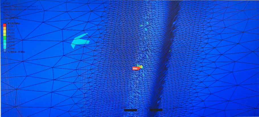
Ansys EmployeeA result picture is not very usefull without some legend and description. I don't know what the above picture is trying to show. Is it deformation, Newton Raphson residuals, stress? What is the scaling? At high scaling value for any result can make things look weird. It's always best to look at true scale as a reference first, then use a larger scaling factor to make out better what's happening.
There are probably fillet faces here nicely running in certain directions, and you could probably set a "Face Meshing" control to get a mapped mesh if they are 4-sided. You may need to set edge sizings to set same number of divisions on opposite sides of the face. This will get you nicely running grid lines, with high quality quad elements. But I will note this issue doesn't look like a problem of the mesh quality.
Look at warnings and errors during the iterations in the Solution Information. Especially what is the final error causing the analysis to terminate? Are there no substeps converged? Or do you have partial solution where you can view stress/deformation until the time when it stops running? In a partially converged solution, the end time may show something but it's not realistic. Just view the results for converged substeps. It is also possible you have a small stress/strain slope for the plastic portion of the bilinear material, and the material is just deforming quickly once in that plastic zone. Check some probes for stress values. Also the plastic slope of the bilinear material should be positive and non-zero.
-
- The topic ‘Problems with meshing in static analysis’ is closed to new replies.


-
4838
-
1587
-
1386
-
1242
-
1021

© 2026 Copyright ANSYS, Inc. All rights reserved.


