TAGGED: crack, crack-analysis, fracture, fracture-mechanics, Path Analysis
-
-
March 22, 2024 at 4:22 pm
user deleted
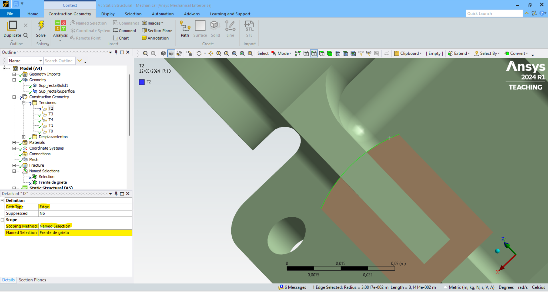
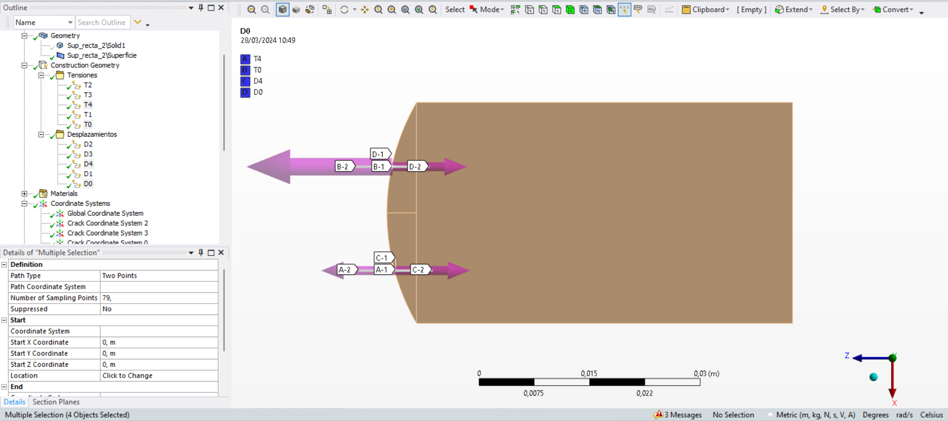
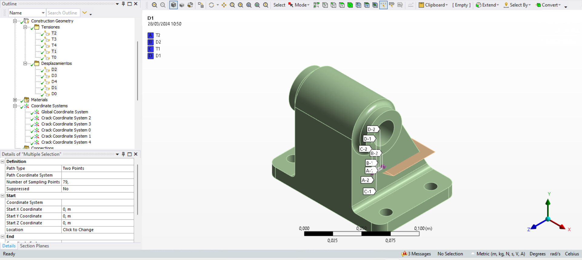
SubscriberHola a todos,Tengo un problema al definir un camino en un lado curvo perteneciente a una superficie definida con tratamiento "Construction Body" para luego simular una grieta usando el módulo Ansys Fracture. La idea es que el frente de grieta sea curvo para lograr un modelo más realista, en comparación con otro modelo con un frente de grieta recto. En este último no he tenido ningún problema porque he definido el camino por dos puntos. Sin embargo, el camino definido por dos puntos en el lado curvo no se genera correctamente (imagen 1). He intentado definir el camino usando el método "borde" en lugar de usar el método "dos puntos", para hacer esto tengo que definir una "Selección con nombre" pero no permite seleccionar el lado correctamente (imagen 2) . ¿Alguien me puede ayudar? ¿ayuda?Muchas gracias por adelantado.Mis mejores deseos,José GargalloFigura 1.Figura 2. -
March 27, 2024 at 2:48 pm
Ashish Khemka
Forum ModeratorTranslated:
Hello everyoneI have a problem defining a path on a curved side belonging to a defined surface with "Construction Body" treatment and then simulating a crack using the Ansys Fracture module. The idea is that the crack front is curved to achieve a more realistic model, compared to another model with a straight crack front. In the latter I didn't have any problems because I defined the path by two points. However, the path defined by two points on the curved side is not generated correctly (image 1). I have tried to define the path using the "edge" method instead of using the "colon" method, to do this I have to define a "Named Selection" but it does not allow you to select the side correctly (image 2). Can anyone help me? help?Thank you very much in advance.Best wishesJosé GargalloFigure 1.Figure 2. -
March 27, 2024 at 3:41 pm
danielshaw
Ansys EmployeeWhy are attempting to create a path? What type of crack are you using?
-
March 27, 2024 at 6:58 pm
user deleted
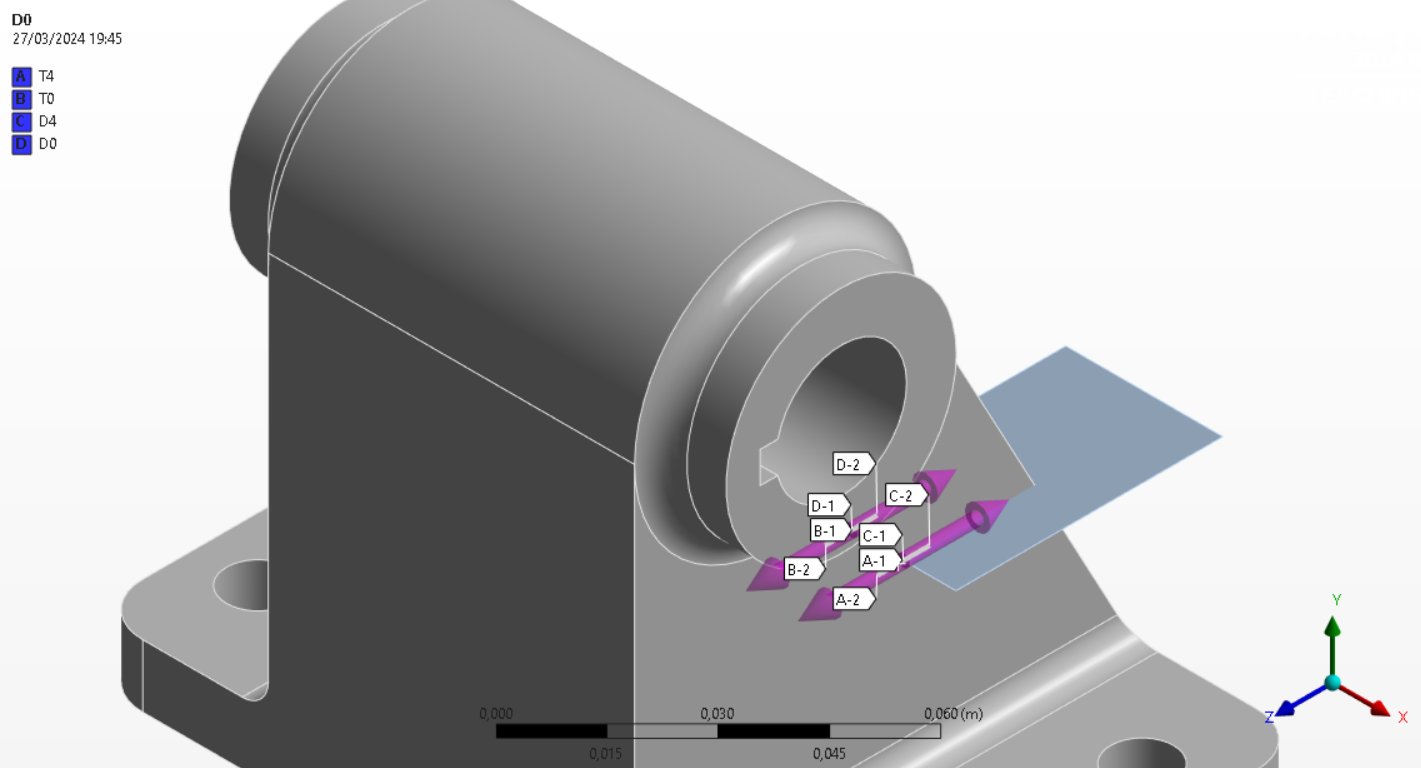
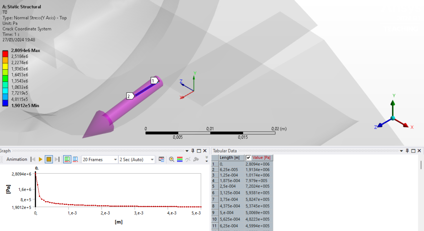
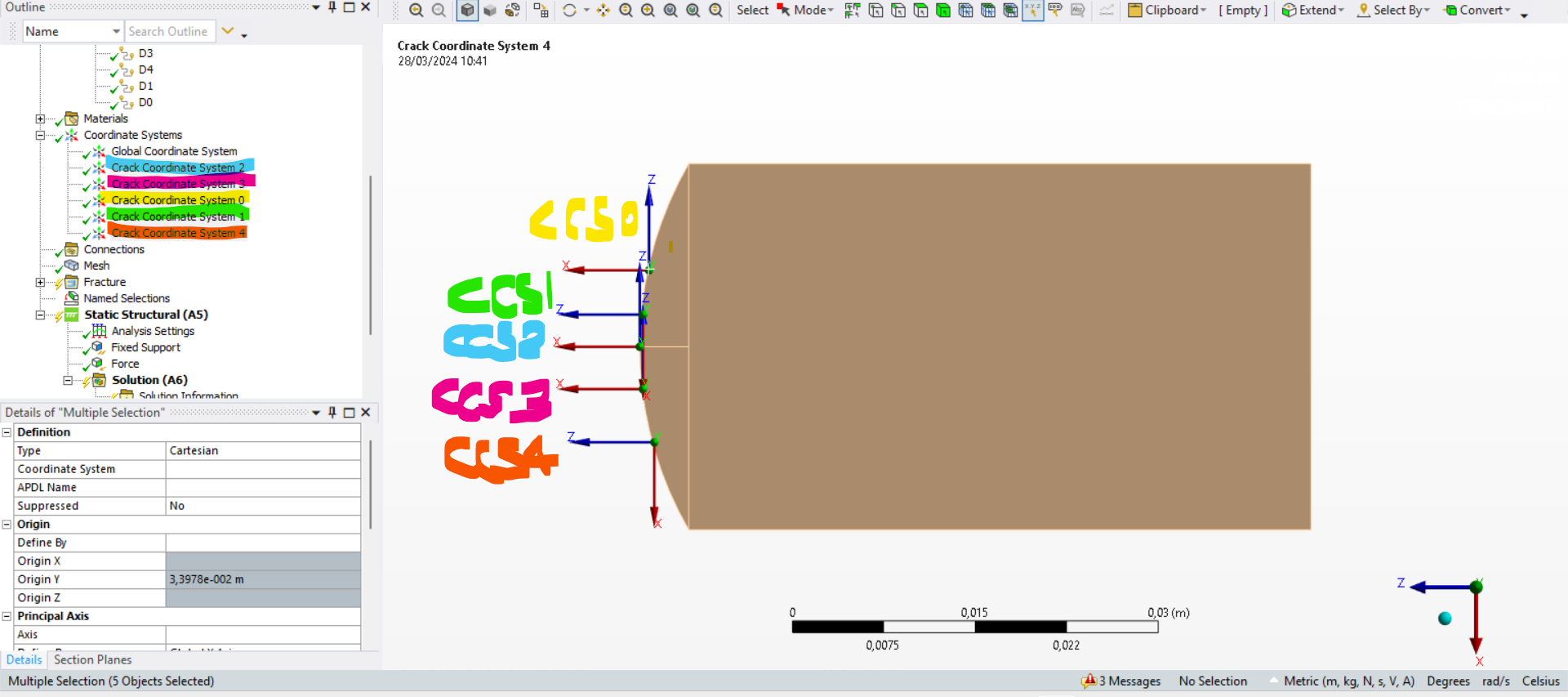
SubscriberDear Daniel Shaw,I want to apologize for the confusion in my previous message. My objective is to compare the results of K1, K2 and K3 obtained through local stress and displacement extrapolation methods with the values obtained through the fracture modulus. For this, I need to define paths close to the crack front and extract the stresses and displacements in the Y direction along these paths in Excel. Then I need to process the data to get K1 and compare it with the Ansys results.I have attached some images showing what I have achieved so far on a rectilinear crack front model.This process is relatively simple on flat surfaces with straight crack fronts, but becomes more complicated when the front is curved. In this case, the z-axis of the crack coordinate system, which must be tangent to the front line, is constantly changing, making it difficult to define the trajectories. I hope I have explained myself better this time.I'm working with an arbitrary crack.I appreciate your help in advance.Kind regards,Jose Gargallo -
March 27, 2024 at 7:13 pm
danielshaw
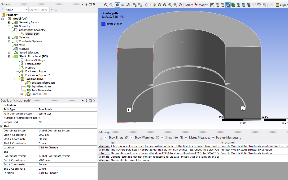
Ansys EmployeeYou have limited options to create paths. Basically you can use 2 points or an Edge. Using an edge should work. It is not clear why it did not work for your model. You can create a curved path using 2 points and a cylindrical coordinate system rather than a cartesian system. Can you create the path that you need using local cylindrical coordinate system?
-
March 28, 2024 at 9:50 am
user deleted
SubscriberHello Daniel,Thank you very much for your help with my problem. I have been reviewing the options that you mentioned to me and, indeed, the edge method does not allow me to create the paths perpendicular to the front of the crack that I need to create to use the local methods of extrapolation of stresses and displacements of the theory related to the Fracture Mechanics that I am researching...I have been thinking about an alternative and think the best option is to define the paths using the points method. However, I am worried that this process will be too tedious and slow since I would have to manually extract the coordinates (x, y, z) of each point.My question is: Is there a way to simplify this process? Is there a tool or command in Ansys that allows me to create more efficient paths perpendicular to a surface?I've attached new images to complete those in my previous answer so you can better understand the problem I'm trying to solve.Any suggestions or comments are welcome.Again, thank you very much for your time and attention.Kind regards,José Gargallo Tatay -
March 28, 2024 at 7:55 pm
danielshaw
Ansys EmployeeI do not know any techniques to automate path creation other than maybe creating an extension using Python scripting. I doubt that creating an extension is worth the effort unless it can be use on many models. I also cannot help you with any scripting, but there is an ACT extensionon on the Ansys App store that does automatic path creation. That App is old and may not run in current releases, but you could download it and maybe get some ideas from it.
https://catalog.ansys.com/product/5b3bc6857a2f9a5c90d32ea2/pressure-vessels-a
-
- The topic ‘Problem with the definition of a path on a curved side’ is closed to new replies.


-
5094
-
1830
-
1387
-
1248
-
1021

© 2026 Copyright ANSYS, Inc. All rights reserved.


