3D Design

3D Design

Topics related to Ansys Discovery and Ansys SpaceClaim.

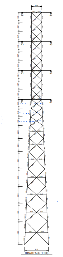
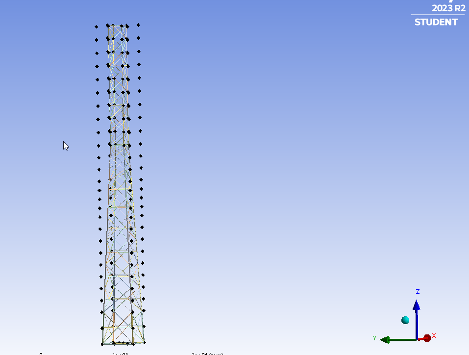
Problem with Shared Topology or contacts in a Lattice Communication Tower

    • Suhi Suhaas
      Subscriber

      I have created this tower in Ansys Design Modeler. The problem right now I am facing is with the shared topology or contact issues near the junction of main legs of tower where the tower changes its profile from TAPERED to UNIFORM at 25m of Height.(You can see that in above drawing). [used SHARED TOPOLOGY IN Design Modeler]


      I have run a MODAL ANALYSIS so that I can understand which elements are flying off to determine weak contacts. 

      As you can see in the above the GIFs The line bodies are flying off. What modifications should be made to deal with this issue. Please help me.

    • peteroznewman
      Bbp_participant

      Try adding a Mesh Edit to insert a Mesh Merge to merge the nodes at each end of those loose beams with nodes on the adjacent beams.

    • Suhi Suhaas
      Subscriber

      I did it. It worked. But the frequency is still Zero(0). How to get Frequency >1 as its required. And Also, I cant calculate the Beam results due to errors. 

      Static Structural Errors :

      1. An internal solution magnitude limit was exceeded. Please check your Environment for inappropriate load values or insufficient supports.  Please see the Troubleshooting section of the Help System for more information.

      2. An internal solution magnitude limit was exceeded. (Node Number 1, Body Level 1.1, DOF UX) Please check your Environment for inappropriate load values or insufficient supports.  You may select the offending object and/or geometry via RMB on this warning in the Messages window.  Please see the Troubleshooting section of the Help System for more information.

      Warnings :

      1. Solver pivot warnings or errors have been encountered during the solution.  This is usually a result of an ill conditioned matrix possibly due to unreasonable material properties, an under constrained model, or contact related issues.  Check results carefully.
      2. Line bodies with type set to Link/Truss or Cable may not be able to solve if Large Deflection is turned off in the Analysis Settings for the model. (I turned this ON)
    • peteroznewman
      Bbp_participant

      Run Modal analysis again and plot the first six modes. If the modal frequency is practically zero, that means you have more beams that are loose. The deformation plot Details window will list the name of the component with the maximum deformation. Merge those nodes and repeat the process until the first mode has a real frequency, assuming you have added supports to the base of the tower.

      Did you set any of your line bodies to Link/Truss or Cable?  I expect that all your line bodies are set to Beam elements. Is that correct?

    • Suhi Suhaas
      Subscriber


      Internal Elements i.e., Line Bodies other than 4 Main legs are set to Link/Truss elements.(This is the requirement I can’t avoid). The Main 4 legs are set to Beam Element from the bottom of the tower to the top of the tower.


      Yes, I have added FIXED support to the base of the Tower. 

      As the ERRORS are suggesting a problem with line bodies; I have been fixing those errors using CONTACT TOOL and its in the process. As you have said earlier, there are lots of truss elements/line bodies that have contact issues. Could you please suggest a better or efficient way of dealing with contact related issues

    • peteroznewman
      Bbp_participant

      Apply a Mesh Sizing control to all line bodies that have Link/Truss elements and set the Number of Elements to 1.

      Having more than one Link element between the endpoints makes the stiffness matrix ill-conditioned for solving.

      There should only be a single line body between the beam vertices that is assigned Link/Truss as multiple line bodies will create the same problem.

Viewing 5 reply threads
  • You must be logged in to reply to this topic.