TAGGED: 1-way-fsi, 2-way-fsi, ansys-apdl, ansys-fluent, boundary-conditions, mismatch
-
-
August 22, 2022 at 7:48 am
jfonken
SubscriberHi all,
For my PhD project on abdominal aortic aneurysms, I'm using Ansys System Coupling, Ansys APDL and Fluent to perform FSI simulations of patient-specific geometries. At the moment, we're working on obtaining patient-specific inlet velocity profiles to use in the CFD part of the FSI simulation. We want to prescribe this velocity at the inlet of the measured geometry. However, in the solid domain, we need to fix the displacements of the inlet (and outlets) in longitudinal and circumferential direction, which causes some numerical inaccuracies close to the inlet (and outlets). Therefore, we normally extend the patient-specific geometry by a few cm, to reduce the effects of the BCs of the solid domain in the region of interest.
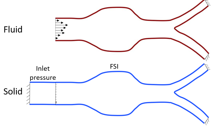
This leads to a mismatch of solid and fluid inlets. To resolve this, I came up with the following idea (see picture):
The red part is the patient-specific geometry, whereas the blue part is the extension at the side of the inlet. In my CFD (Fluent) simulation, I'm already able to create separate mesh zones for the red and blue parts. I want to prescribe the (patient-specific) velocity at the inlet of the red part and prescribe the current inlet pressure to the complete extension (blue). The extension can be exclude from the CFD simulation, only the pressure needs to be updated each step (according to the changes in pressure at the inlet).
However, I don't know how to achieve this. Does anyone have any recommendations on how to handle this problem? Or maybe a different approach to handle the mismatch between the solid and fluid domain?
I also tried another approach (see picture):
The real patient-specific geometry is used in the fluid domain and the velocity is prescribed at the inlet. The extended patient-specific geometry is used in the solid domain and is divided into the patient-specific (right) part and the extension (left). At the patient-specific part, a 2-way FSI interaction is prescribed, in which the pressures calculated in the fluid domain are transferred to the solid domain and the calculated displacements in the solid domain are transferred to the fluid domain. The extension is coupled to the inlet of the fluid domain using a 1-way FSI interface, so only the pressure of the fluid domain is transferred to the solid domain, no displacements are transferred.
However, in this case, no mapping can be performed between the extension and the inlet of the fluid domain, because the meshes aren't conformal.
Hopefully this post is clear to you, I understand it could be quite confusing ?
Please let me know if you have a suggestion!?
Best,
Judith
-
August 22, 2022 at 10:34 am
Danica
Ansys EmployeeHi Judith,
So looking at the problem, you need to define either the inlet pressure or the inlet velocity profile, but not both. A velocity boundary varies the pressure until the velocity condition is met: a pressure boundary adjusts the mass flow until the pressure is met. I would suggest a transient velocity profile defined at a point that is a suitable length upstream of the region of interest to allow for the flow to fully develop. Would suggest velocity over pressure as this will provide more stable solutions.
Have a look at the following for how to define this: 7.6. Transient Cell Zone and Boundary Conditions (ansys.com)
What model are you using for blood viscosity?
Danica
-
August 22, 2022 at 11:17 am
jfonken
SubscriberHi Danica,
Thanks for your reply! I actually don't want the flow to develop any further, because I used Ultrasound Doppler to measure the velocity at the inlet, so I want to prescribe this measured velocity at the correct point (right at the beginning of the region of interest). I understand that I can't prescribe both inlet pressure and inlet velocity, that's why I was thinking about excluding the extension in the simulation, but only using it to transfer the inlet pressure to the solid domain. However, I then need a way to prescribe the inlet pressure to the extension, but I don't know how.
I'm using the Carreau model for the viscosity.
Best,
Judith
-
August 22, 2022 at 1:01 pm
Danica
Ansys EmployeeHi Judith,
I think that you can use an area-weighted average pressure report at the velocity inlet to get the pressure for each time-step. Then import these values into APDL using system coupling and use this value to define the pressure on the solid section of the model.
-
August 22, 2022 at 1:13 pm
jfonken
SubscriberHi Danica,
That's an excellent idea indeed. I didn't know it was possible to import pressure values into APDL for each timestep using system coupling. Do you maybe have some documentation or examples that I can look into?
-
August 23, 2022 at 2:46 pm
Rob
Forum ModeratorThe only documentation we can share via the Community is accessable through Help in the Fluent solver, if you navigate up the tree you'll eventually get to the (nearly) full list of Ansys products.
-
August 24, 2022 at 6:27 am
jfonken
SubscriberHi Rob,
I have access to the Ansys Documentation, but I haven't found a way to import pressures into Ansys APDL using system coupling (yet). Do you have recommendations for certain commands or chapters of the documentation?
-
August 24, 2022 at 2:30 pm
Rob
Forum ModeratorOnly the System Coupling section - I'll ask this side. For most of the work I do it if bends it's going to fail so I don't tend to do any FSI.
-
September 2, 2022 at 6:43 am
jfonken
SubscriberHi Rob,
Have you been in touch with the System Coupling section to resolve this problem?
Best,
Judith
-
-
August 24, 2022 at 3:13 pm
jfonken
SubscriberUsing the *TREAD command, I'm able to import the Fluent pressure values into Mechanical APDL. However, this is only done before the first time step, but then no Fluent pressures are available yet. I would really appreciate any help to update the pressure table during the system coupling simulation. Which command(s) should I use to issue the *TREAD command (updating the pressure table) at every coupling step?
-
September 2, 2022 at 8:37 am
Rob
Forum ModeratorWe did, I'll remind them.
-
September 6, 2022 at 6:06 am
jfonken
SubscriberOkay thanks, hopefully they can help me!
-
September 13, 2022 at 11:42 am
jfonken
SubscriberHi Rob,
Any news from the system coupling section?
-
September 13, 2022 at 1:46 pm
Rob
Forum ModeratorIt would appear not, I'll try kicking again. My apologies.
-
September 14, 2022 at 8:56 am
Rahul
Ansys EmployeeHi Judith,
Sorry for the delayed response.
Please refer External Data (ansys.com) to import data from text files into a Mechanical system or a System Coupling component system.
-
September 20, 2022 at 11:25 am
jfonken
SubscriberDear Rahul,
Thanks for your input. I had a look at the referred documentation. However, it states that the external data is static and therefore only read in the analysis set-up. I was able to do this with the *TREAD command as well, but my problem is that it doesn't re-read the file at each coupling (time) step. Do you have any suggestions to solve this problem? Which command(s) should I use to issue the *TREAD command (updating the pressure table) at every coupling step? For Ansys APDL, it works well to use the *TREAD command at each load step, but Ansys APDL sees the system coupling process as a single load step.
Best,
Judith
-
-
-
September 22, 2022 at 10:37 am
Rahul
Ansys EmployeeHi Judith,
Both external data and *TREAD command will work for static data import and even if loaded data at each load step in APDL, SC will process it as single step.
-
September 22, 2022 at 10:59 am
jfonken
SubscriberHi Rahul,
I indeed had this experience. Isn't it possible to alter something, such that SC will consist of multiple steps, such that new data can be loaded in each step?
-
-
September 23, 2022 at 12:26 pm
Rahul
Ansys EmployeeHi Judith,
When a co-simulation coupling participant, such as a Fluent system, is connected to a Mechanical
system via System Coupling, Mechanical is given access to data directly from the other participant. So, I would suggest you to create conformal mesh and specify the velocity at the extended part and transfer data directly from Fluent to Mechanical through system coupling.Regards,
-
September 23, 2022 at 12:33 pm
jfonken
SubscriberHi Rahul,
As explained in my initial question, when I prescribe the velocity at the extended part, the profile developes and therefore deviates from the measured profile at the measurement site. I was unable to prescribe a pressure at the extension part in Fluent, as schematically represented in the figure below. Do you have any suggestions on how to achieve this?
-
September 28, 2022 at 10:47 am
Rahul
Ansys EmployeeHi Judith,
As you wants to import the external data in MAPDL. External data won't get updated due to coupling it with MAPDL. In that case you can try one way coupling between the external data and MAPDL. You can add multiple data sets with external data in that case. Please refer "Importing Multiple Data Sets" section in External Data (ansys.com)for more information.
-
-
-
October 3, 2022 at 9:45 am
jfonken
SubscriberHi Rahul,
Is there also an option to "tell" System Coupling that it should update Mechanical APDL each timestep?
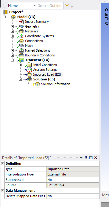
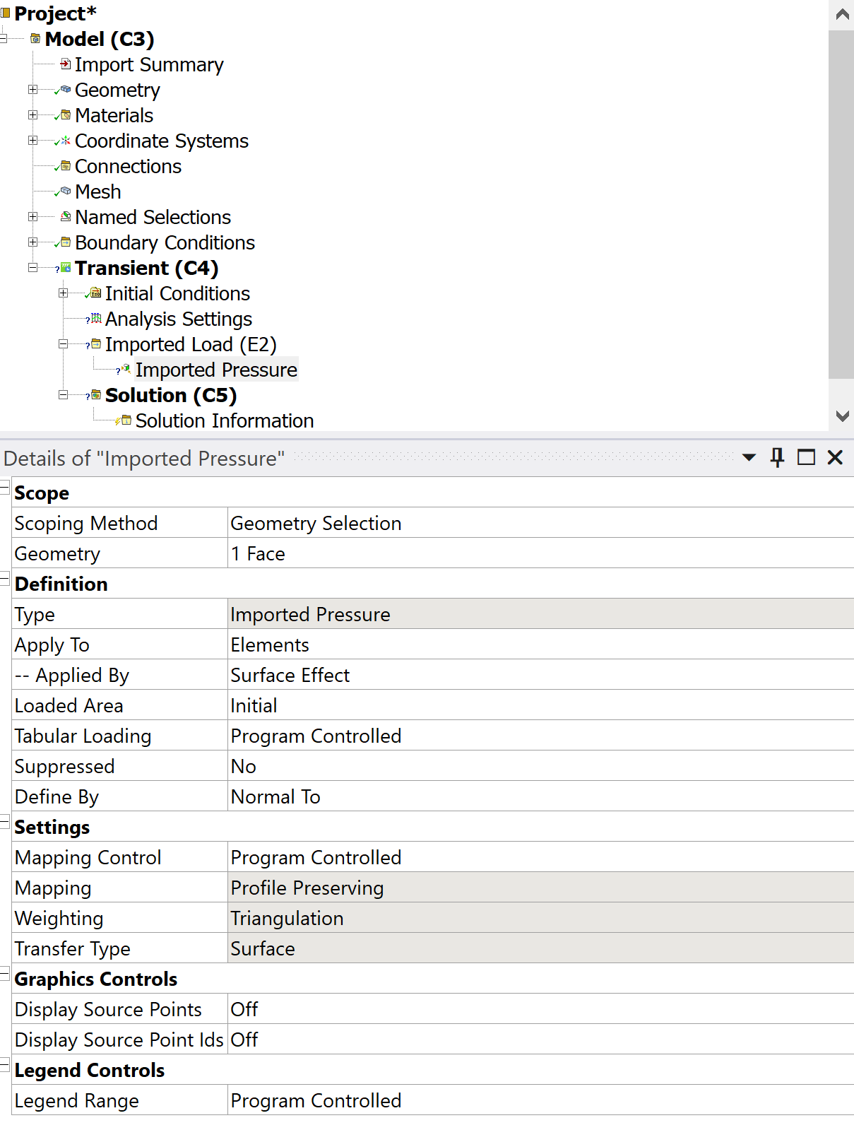
I'm having some problems importing the data in Workbench, although I followed the documentation. My external data tab looks fine (see figure below).
However, I can't access the (individual) files/pressure values in the transient structural model, to add as load in specific timesteps. Any suggestions on how to resolve this?
-
October 3, 2022 at 10:12 am
-
October 3, 2022 at 1:32 pm
-
October 13, 2022 at 11:40 am
jfonken
SubscriberHi all,
Unfortunately, I'm still struggling with this problem. The easiest way (in my opinion) is to be able to isssue the *TREAD in Ansys Mechanical at each coupling step. Is there really no possibility to tell system coupling to not treat Ansys Mechanical as a single step?
And if this is indeed not possible, would it be possible to prescribe the inlet pressure in the complete extension domain?
Ansy help would be greatly appreciated, since I've been struggling with this problem for quite some time.
Best,
Judith -
October 18, 2022 at 4:09 pm
Stephen Orlando
Ansys EmployeeHi Judith,
I have a few more thoughts here on possible solutions.
Run some fluid only simulations, to determine the inlet velocity profile at the extension that produces the desired inlet velocity profile at the fluid inlet. Then run the FSI simulation where the fluid and solid interfaces are conformal and use the newly calculated inlet velocity profile at the extension.
It should be possible to use a command snippet in Mechanical to read a report file from Fluent that has the inlet pressure and get the inlet pressure at every timestep. Someone from the Mechanical support team will need to help with this. I’m not sure if *TREAD will work or not.
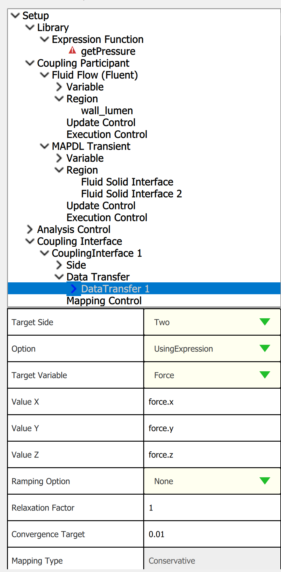
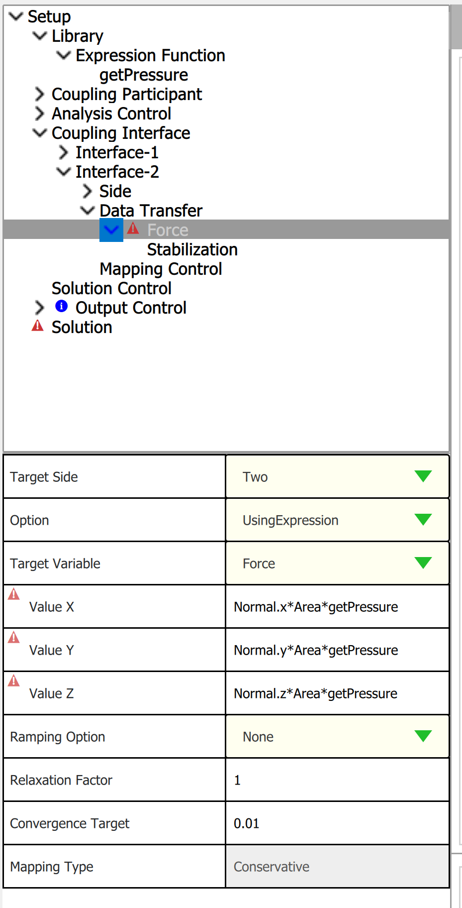
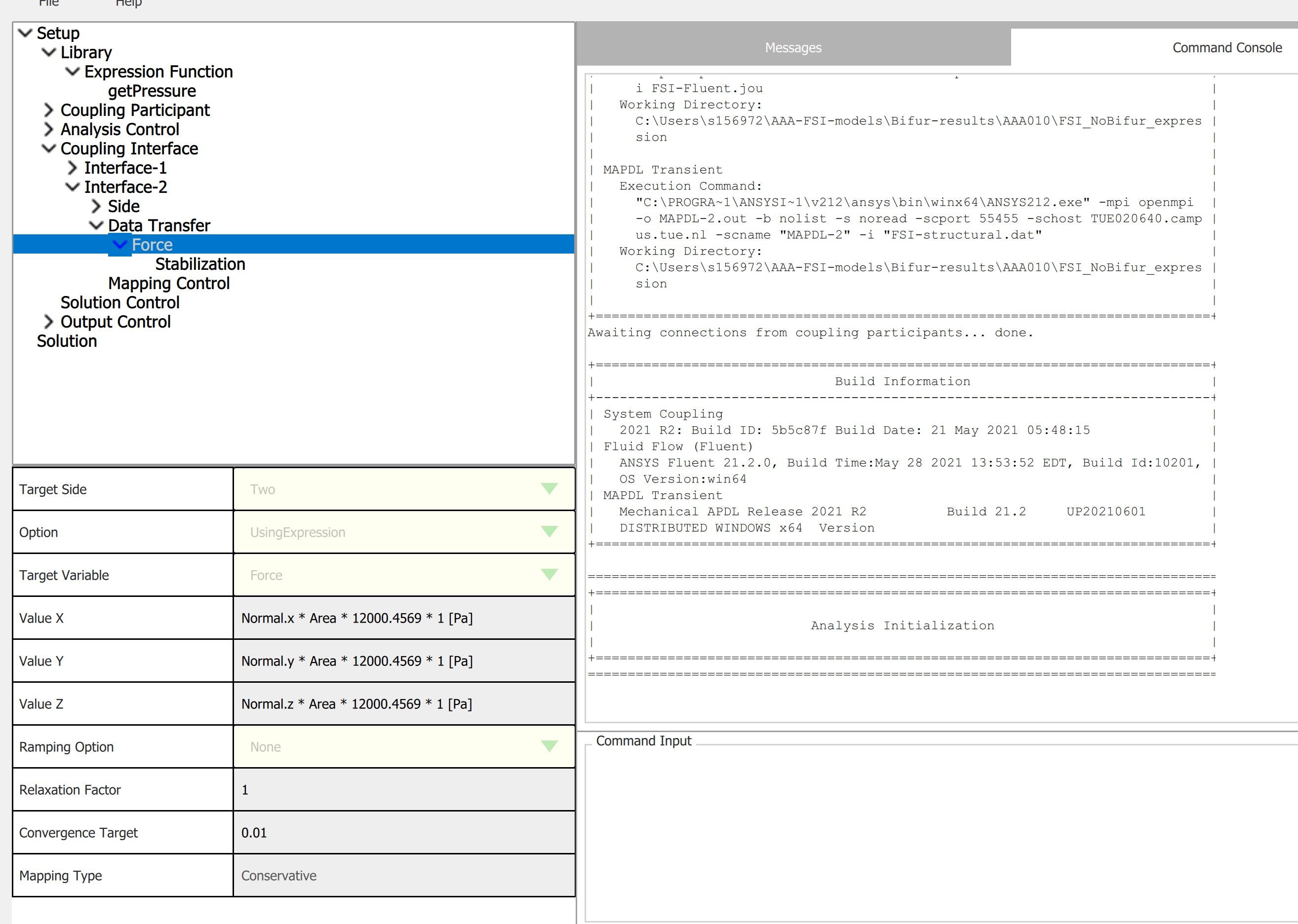
- It may be possible to send pressure data to the extension region by adding a second coupling interface for the extension region. I haven't tried this yet, but it's worth trying. You could then use Expressions in System Coupling outside of Workbench to apply a custom force as shown below. Here Area is a built in variable which is a field variable for the area of each face on the target surface. getpressure would be a Python function that would need to read a Report File from Fluent that has the inlet pressure. More info on Python functions here: Expressions in System Coupling (ansys.com)
-
October 19, 2022 at 7:07 am
jfonken
SubscriberHi Stephen,
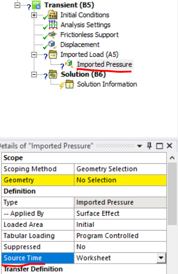
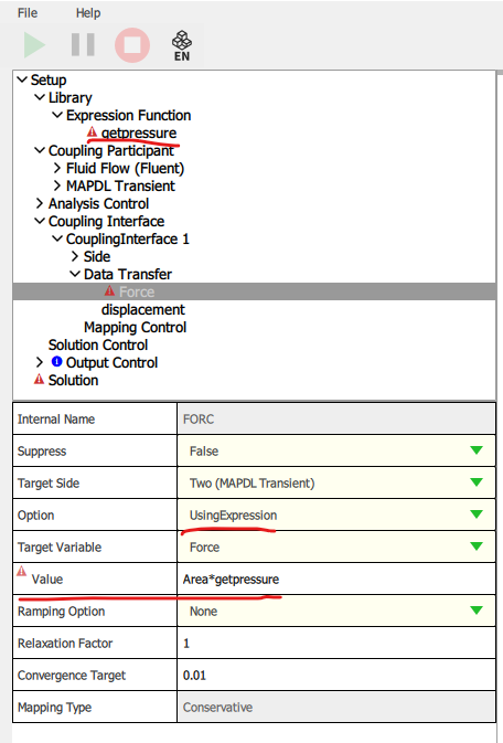
Thanks for your input on possible solutions. I’m in contact with an Ansys APDL employee, so hopefully he can help me with option 2, is a code snippet is available. Meanwhile, I’ve been exploring option 3. However, I’m not getting the same interface as you do. In my case (see figure below), I can only presribe the directional forces and it doesn’t use the ‘getPressure’ function. Maybe I’m missing some input for the ‘getPressure’ function, or I’m using a different version of SC as you do. Which version are you using and could you send me a screenshot of the details of the ‘getPressure’ function?
EDIT: in my case, both displacements as force are specified as vector. This explains why I need to evaluate the X,Y and Z directions separately. However, the pressure is a scalar that should be applied perpendicular to the wall. How could this be achieved?
Best,
Judith
-
October 19, 2022 at 9:50 am
jfonken
SubscriberHi Stephen,
I'm now able to add a module with the 'getPressure' function and adjust the expression for the values. Using the Normal variable that is available within SC in the specified direction, I believe that I can correctly convert the pressure to the force components. I only get the warning that the expression units are not consistent with the expected units. I believe this is caused by the fact that SC assumes 'getPressure' to be dimensionless, so it only sees the 'Area' dimensions. I still have to write the 'getPressure' function to really output the pressure (next step), so that may cause the problem. Do you know if it's necessary to specify the units of the expression function? And if yes, how I can do this?
Best,
-
October 19, 2022 at 1:50 pm
jfonken
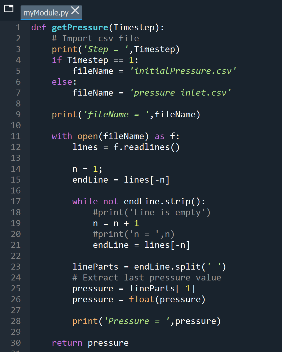
SubscriberSorry for the spam? I was able to create a simple Python script that reads in the csv file containing the pressures and returns the last pressure value in the file. This should be repeated each timestep, hence the 'Timestep" argument. I tested it in Spyder and it works perfectly, also when the file is continuously updated.
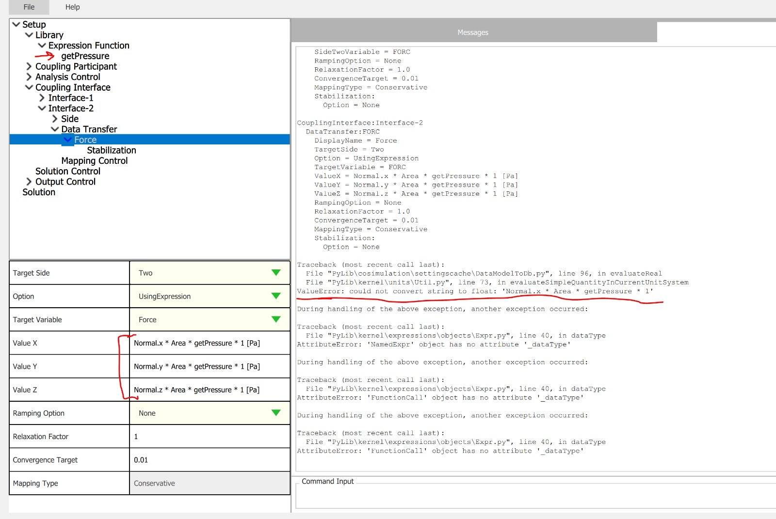
Next, I've added this function to the SC set-up and created an expression for the values in X,Y and Z direction, based on the pressure derived from the Python script/csv file. To match the dimensions, I added " 1 [Pa]" as I've seen in the SC documentation. However, when running the SC program, I got a Value error saying: "could not convert string to flot: 'Normal.x * Area * getPressure * 1'. However, the pressure was converted from string to float in the getPressure function.
To check if the getPressure function is causing the problem, I also ran a SC simulation while specifying a pressure (with decimals). This run didn't give a value error, but did lead to a fatal error in MAPDL, indicating that No data transfer sets are defined in system coupling. Could this have to do with the 1-way coupling that is specified now (so only forces are imported using the function, but no displacements are transferred)?
Since I have little experience with Python coding and even less experience with hooking Python code to Ansys SC, any help would be greatly appreciated!
Best,
Judith
-
October 19, 2022 at 6:51 pm
Stephen Orlando
Ansys Employee-
October 20, 2022 at 5:48 am
jfonken
SubscriberHi Stephen,
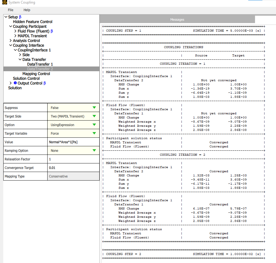
I'll try in version 2022R1 or 2022R2 (dependent on what's available). Is their a reason that you work in Beta version? And what is included in DataTransfer1? Are the displacements transferred to Fluent? Cause that wouldn't be possible in my situation, since no extension is included in Fluent.
Best,
Judith
-
-
October 20, 2022 at 7:15 am
jfonken
SubscriberIn version 2022R1, I don't get an error, but my simulation is stuck. Would it be possible to send you all input files, such that you can test if it works on 2022R2?
-
October 20, 2022 at 12:34 pm
jfonken
SubscriberThe link below can be used to download my files. It would be great if you could test it on 2022R2! If that works, I can request the new release.
https://tue.data.surfsara.nl/index.php/s/FNIkDtbDqeKJGu9
-
-
October 20, 2022 at 6:29 pm
Stephen Orlando
Ansys EmployeeHi Judith,
Beta isn't needed for what I've shown. Also, I've shown Data Transfer 1, but it isn't needed. Unfortunately Ansys employees can't download files from the forum.
Stephen
-
- The topic ‘Problem with partial overlap of solid and fluid domains in FSI simulation’ is closed to new replies.


-
4618
-
1530
-
1386
-
1209
-
1021

© 2025 Copyright ANSYS, Inc. All rights reserved.


