-
-
December 16, 2023 at 11:19 am
javat33489
SubscriberHi all.
I'm modeling an inflating rubber. The problem is axisymmetric. It is installed in a pipe. The left end is fixed, the right end can move along the axis (there is a lock). Pressure 7 MPa, material NEO Huquean.
During the calculation, everything goes well, but at 50% of the load the calculation stops due to the mesh breaking, and in the most unexpected place, where a thin spot (hernia) occurs. If you look at the Newton Raphson residuals, everything points to this place. Newton Raphson residuals do not indicate contacts.
All contacts are debugged, Normal Lagrange. Convergence control for displacement, moment and force is turned on by 5%. All simple settings are taken into account (large reflection, etc.). The type of solver I use is Program Controlled (I also tried Direct and Iterative). The mesh always breaks there (distortet error).
I tried everything:
changed the contact method (normal and augmented Lagrange)
changed contact detection
added dumping in contacts
I also added general damping with constant = 0.02 (in this case the rubber does not deform at all)
I changed the mesh type (nonlinear mechanics and mechanics)
I changed the grid size (quadratic and linear)
I tried remeshing the mesh according to the given parameters
I also added KEYOPT, matid, 6, 1 to the material
I used all possible life hacks, but the grid breaks down there.
Why? Please help me with advice, what else can be done there? -
December 17, 2023 at 10:23 pm
peteroznewman
SubscriberWhere did the 7 MPa pressure load come from? That is a very large pressure. My car tires take only 0.2 MPa of pressure.
What is the axis of revolution for your figure? Is it horizontal?
What is the axis of revolution for your geometry? It must be the Y axis. Is that what you used?
-
December 18, 2023 at 1:56 am
-
-
December 18, 2023 at 11:03 am
peteroznewman
SubscriberIs the free state of the rubber in the shape of a pipe also, or is it molded into a shape close to the shape you sketched? If the rubber starts out as a straight pipe, it is not accurate to draw the deformed shape to start the simulation. It is more accurate to draw it as a straight pipe and deform it into the shape you want so that the internal stresses are calculated correctly.
The sharp corner at the end of the pipe could be a problem if the rubber makes contact with the sharp edge. For a diagnostic check, try making the pipe longer to avoid the sharp edge. Mesh the rubber with 8 linear elements across the wall thickness and set the element size to 1/8 of the wall thickness to get nearly square quad element shapes. You may be able to use either a Face Meshing control or a Sweep method to achieve this.
If the pipe has to end as shown in the sketch, radius the sharp edge at the end of the pipe. When you do that, you will need smaller elements on the rubber so that at least four nodes will be able to wrap around the radius when the pressure pushes the rubber out.
-
December 18, 2023 at 5:18 pm
javat33489
SubscriberThank you for your answers and advice sir. But I've used them all.Â-
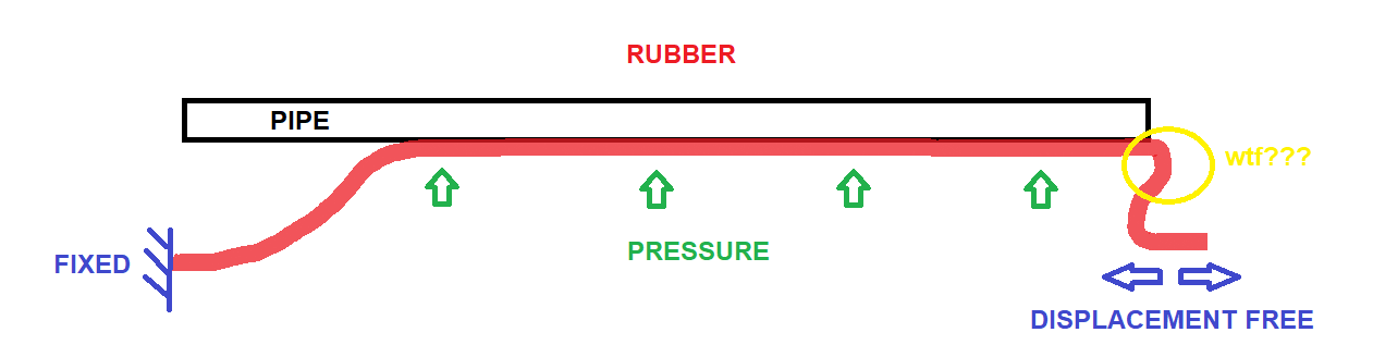
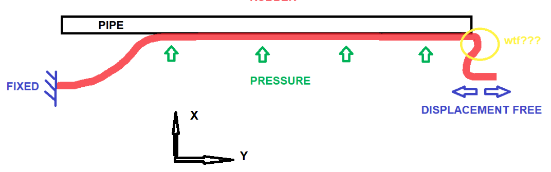
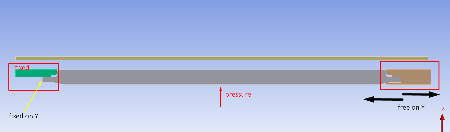
Yes, initially the rubber is in the shape of a pipe, it is located in a large pipe and is inflated in it.-
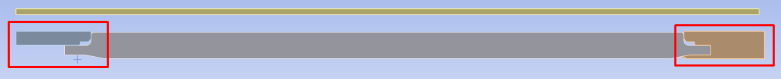
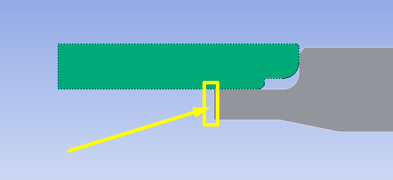
There are no sharp edges, rubber does not touch sharp edges - this is basic knowledge for calculators.-The grid is linear, at least it has 8-10 elements, it is well structured.-
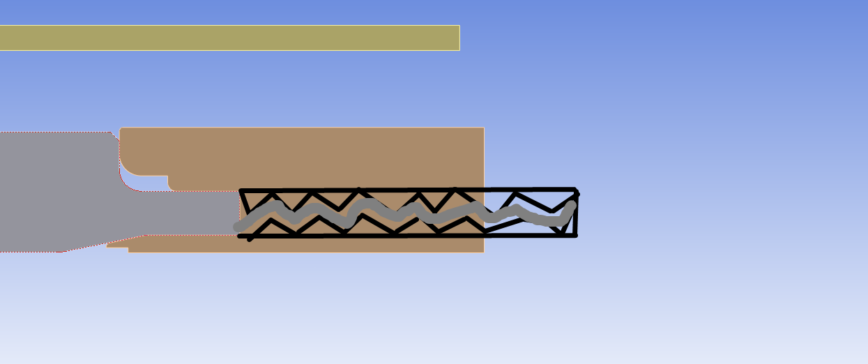
Where the rubber touches the elements, the elements are rounded and the mesh in these places is crushed to 0.01 mm.Â
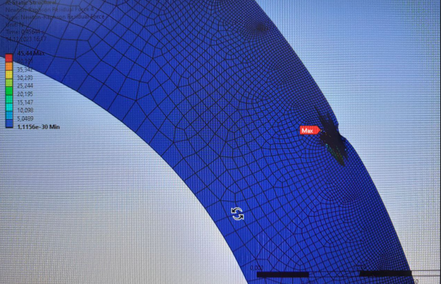
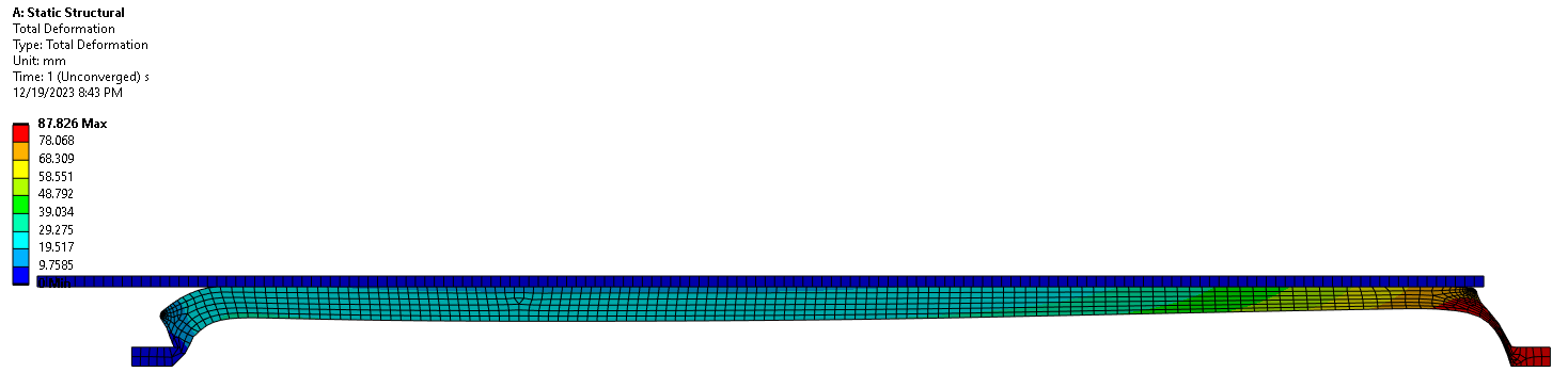
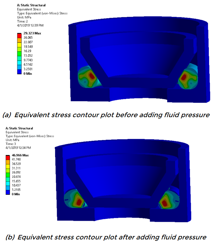
The mesh still collapses at the bend as in the screenshot above.Could it be an energy issue? Or in the material, could this mean that the material is no longer able to stretch? Or will static analysis drag out the details a lot?ÂA question. What to do if the mesh is already very much crushed to 0.01, the contact is flat without convex parts (where the rubber touches the large pipe when it is inflated with its larger flat part), the contact is without penetration, Normal Lagrange, a dumping factor of 0.02 is included, but there are discrepancies in Newton Rawson is still pointed out to this contact. Could it be an energy issue? What life hacks are there to improve contact? -
December 18, 2023 at 8:24 pm
peteroznewman
SubscriberI see over 30 elements through the thickness, not the 8 elements I suggested.
You say there are no sharp edges, so the pipe wall shown in your sketch is too short and should extend much further to the right?
One end of your rubber tube has a Fixed Support. What is the support at the opposite end? Does that edge have X = 0 and Y = Free?
I suggest you draw the rubber as a straight tube and not draw any bends in it. How would the pressure cause the rubber to have a back-bend if it starts out straight?
-
December 19, 2023 at 4:41 pm
javat33489
SubscriberSIR I uploaded the task archive to the cloud. It shows all the loads, contacts and connections that I want to solve, and there are also two types of rubber: soft (50 Shore) and hard (80 Shore). The right end moves freely in the clamp. Please look, I haven’t been able to solve this problem for a month now. I will be very grateful! Thank you!
-
December 20, 2023 at 1:46 am
peteroznewman
SubscriberI stripped your model down to the essential features you show in your sketch.
Here is my ANSYS 2023 R1 archive. Â https://jmp.sh/qCf3Nbza
-
December 20, 2023 at 2:25 am
javat33489
SubscriberThank you very much, you are the best!
But I have questions:
-could you look at the problem along with the clamps? This is very very important.
-could you look at the problem with the second step? This is very very important.Perhaps the problem lies in the clamps and I need to solve it :((
Thanks a lot.
-
December 20, 2023 at 2:13 pm
peteroznewman
SubscriberPlease explain how the clamps work.
-
December 20, 2023 at 5:06 pm
javat33489
SubscriberHello sir!My geometry is a simplified version of the clamps.The essence of the design is that inside a large pipe there is a small pipe. A rubber cylinder is placed on the small pipe; there are metal clamps on both sides of the rubber that prevent the rubber from swelling at the edges. First, the pressure inflates the rubber inside the large pipe, it seals the space, then we apply pressure in the second step so we simulate the work of a seal under pressure.ÂOn the left the clamp is fixed, on the right the clamp moves freely to allow the rubber to swell from the pressure inside in the first step.ÂThe clamps should be the same as on the right, but on the left I simplified it because the lower part does not play a role.ÂThe clamps are simplified in my model; in fact, in real life there are sharp teeth and glue that press the rubber against the walls and prevent it from coming out:ÂI simplified the clamps and secured the rubber on the left - from moving only along the Y and on the right - I added a separation contact so that it could also be compressed along the wall but not separate from the clamp; this allows the clamp to be moved by the rubber.ÂAfter solving this, I also need to look at the force reaction on the left side of the clamp, with what force the rubber is pulled out of the clamp after going through two pressure steps: -
December 21, 2023 at 1:46 am
peteroznewman
SubscriberIs the rubber tube molded with the features you have shown? Or does the shape you drew represent the compressed shape of the rubber tube? I understand there is a portion of the tab that is glued and clamped in teeth and you are not modeling that portion. Instead you have a boundary condition where you cut that portion out of the model.
There is a more sophisticated method for solving for the potential for leakage of a fluid past a seal than the simple method of applying pressure to a predefined length of the interface. It works well for an O-ring in a groove where the fluid pressure pushes on the O-ring, which increases the pressure elsewhere, helping to prevent leaks. In your configuration, since it is a long slender tube that has an internal pressure, any external pressure larger than the internal pressure would tend to cause a leak. Look at this course and be sure to download the file and investigate.
-
December 21, 2023 at 2:09 am
javat33489
SubscriberSir I have seen all the courses. I also received training in nonlinear analysis. It doesn’t work out, my hope is that someone can solve it for me.
-
December 21, 2023 at 2:16 am
peteroznewman
Subscriber -
December 21, 2023 at 4:50 pm
javat33489
SubscriberThanks for your reply sir.
Of course, I understand what you are talking about; this is the fluid pre-penetration (FPP) function. I use it often. In this case, I used remixing, so I didn’t use FFP. FFP does not work with remeshing. I have done many tests and often FFP can be replaced by simply applying pressure, my case fits this.
The problem is that I can't even get to the second step with pressure #2. I constantly have calculation errors. I tried all the methods and options, all the life hacks. It happens that some calculation simply cannot be solved for a long time and only another calculator who can solve this problem can help. I would really like you to solve it. At least the first step. Because I've tried everything and I can't think of anything else to do. Thank you sir!P.S. Sir I have looked at all the training files. I received additional training in nonlinear analysis. I have also solved more complex problems. But for some reason I'm stuck with this problem and it can't be solved. I'm very upset.
-
January 11, 2024 at 7:51 pm
javat33489
SubscriberSir, were you able to solve this problem? I think it needs to be solved in the transient.
-
January 12, 2024 at 12:18 am
peteroznewman
SubscriberTransient can be helpful in models with an instability where the structure approaches a shape with no static equilibrium, but there is a new static equilibrium on the other side of the instability. It doesn't seem like that is the issue in your model. You can certainly try a Transient solution.
-
January 12, 2024 at 1:49 am
javat33489
SubscriberSir, you said when you have time you will try to solve the problem. Can you find the time please?
-
January 16, 2024 at 5:37 pm
javat33489
SubscriberWhat do you say sir?
-
January 16, 2024 at 7:39 pm
peteroznewman
SubscriberDo you have a failure threshold for the rubber material? What is it? Has the material crossed that failure threshold in step 1? If so, then there is no need to get the solution to progress further. The design needs to change so that the material does not exceed the failure threshold.
-
January 17, 2024 at 1:57 am
javat33489
SubscriberSir I have the results of uniaxial tension and Neo-Hookian model. is that enough? Perhaps I misunderstood you.Â
"failure threshold for the rubber material" - what exactly do you mean?
-
January 17, 2024 at 2:35 am
peteroznewman
SubscriberWhen the material is pulled in a uniaxial tension test, you get a force-displacement curve up to the point when the rubber splits into two pieces. What is the True Strain when the material splits? That is a failure threshold. How does that failure strain compare to the strain in the model results? Is the model showing a strain that exceeds the failure threshold? If so, that design can't support any pressures higher than that ultimate pressure when the strain exceeded the failure threshold. If the model fails to converge past the ultimate pressure, we don't care and it is a waste of time trying to get it to converge.
-
January 17, 2024 at 5:43 pm
javat33489
SubscriberYes, sir.
There is such an indicator during testing: CONDITIONAL TENSUAL STRENGTH = 23.5 MPa.
Are you saying that when the rubber reaches this tension, it will break?
What stress should I look at? According to Mises?
-
January 17, 2024 at 8:22 pm
peteroznewman
SubscriberUltimate Tensile Strength is the normal stress when the part breaks. In a 3D state of stress, von Mises stress correlates with the Yield Strength for ductile materials. I don’t know if there is a better correlation for rubber material failure.
-
January 18, 2024 at 1:54 am
javat33489
SubscriberI didn't understand your point. What should I do? I’ll make a calculation when it stops with an error. Do I need to compare the maximum von Mises stresses with the ultimate tensile stress (obtained during testing)?
-
January 18, 2024 at 3:57 am
peteroznewman
SubscriberInsert a Result for von Mises stress and Max Principal Stress. Look at the chart of maximum value vs time. Does the maximum value go above the Ultimate Tensile Strength before the calculation stops with an error?
If yes, then the part fails (stress exceeds strength) before the calculation stops. In that case, there is no need to work on the error because any simulation time after the stress exceeds the strength is not simulating reality.
If no, then the error is preventing you from simulating additional reality and it is worth doing some work to overcome the error.
-
January 18, 2024 at 4:55 pm
javat33489
SubscriberHello, sir. That's exactly what I did. I have attached a screenshot of a typical calculation stop at the first step, at a loading pressure of approximately 4.5 MPa. Screen of normal pressure and according to Mises:
There is such an indicator during testing: CONDITIONAL TENSUAL STRENGTH = 23.5 MPa. The calculation goes well beyond this figure.
Â
Â
-
January 19, 2024 at 1:40 pm
peteroznewman
SubscriberOkay, this is good to know.Â
Draw a horizontal line on the stress chart at 23.5 MPa. Where that line intersects the maximum stress result, draw a vertical line down to the time axis (or just browse the Tabular data to find the first maximum value that exceeds 23.5 MPa and note the time on that row).
Multiply that time by the pressure. Say the time was 0.48 and the pressure for step 1 is 7 MPa. Therefore the pressure at which the part fails is 3.36 MPa.
Redesign the part to increase the thickness where the peak stress is seen at the time of 0.48. Hope that the new part shape can get to a 7 MPa pressure without exceeding a stress of 23.5 MPa.
This assumes that CONDITIONAL TENSUAL STRENGTH means what most engineers understand strength to mean. Perhaps you can ask the testing lab for a definition of that term.
-
January 19, 2024 at 10:35 pm
Ok Ok
SubscriberHello Peteroz. I am also trying to model a rubber too. And it takes me to use the explicit dynamic environment. But I have a problem.
How to apply a 3d moment in explicit dynamic environments. How can I apply a moment that has 3 components: Mx, My, Mz
I saw an old answer about creating a joint. But as far as I found out, it only allows us to give value to one component. I even thought about using three of such joint loads, but I can’t specify the axis of the application either. (For example, it is always z-axis)
Â
BTW sorry for asking my question here. I posted it, but I did not get an answer for it.
Applying a 3d moment in explicit dynamic environment Mx, My, Mz (ansys.com)
-
January 22, 2024 at 4:31 pm
javat33489
SubscriberThank you very much for your valuable advice sir
-
- The topic ‘Problem with mesh on rubber in static analysis’ is closed to new replies.
-
3447
-
1057
-
1051
-
918
-
896
© 2025 Copyright ANSYS, Inc. All rights reserved.