-
-
February 5, 2024 at 6:19 pm
javat33489
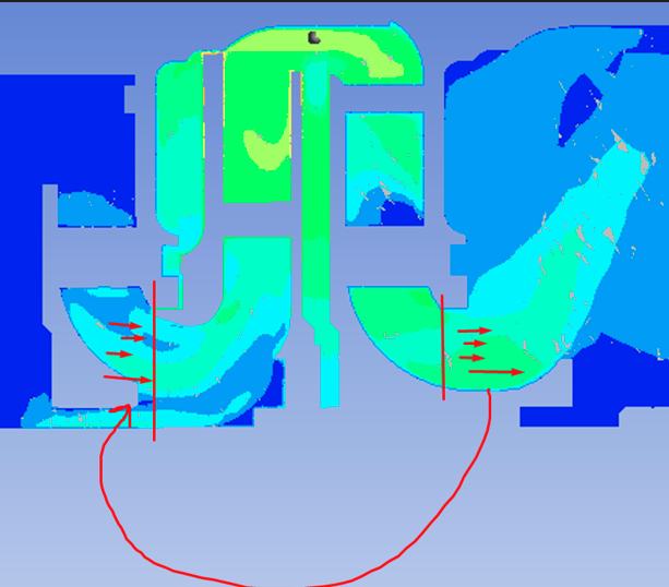
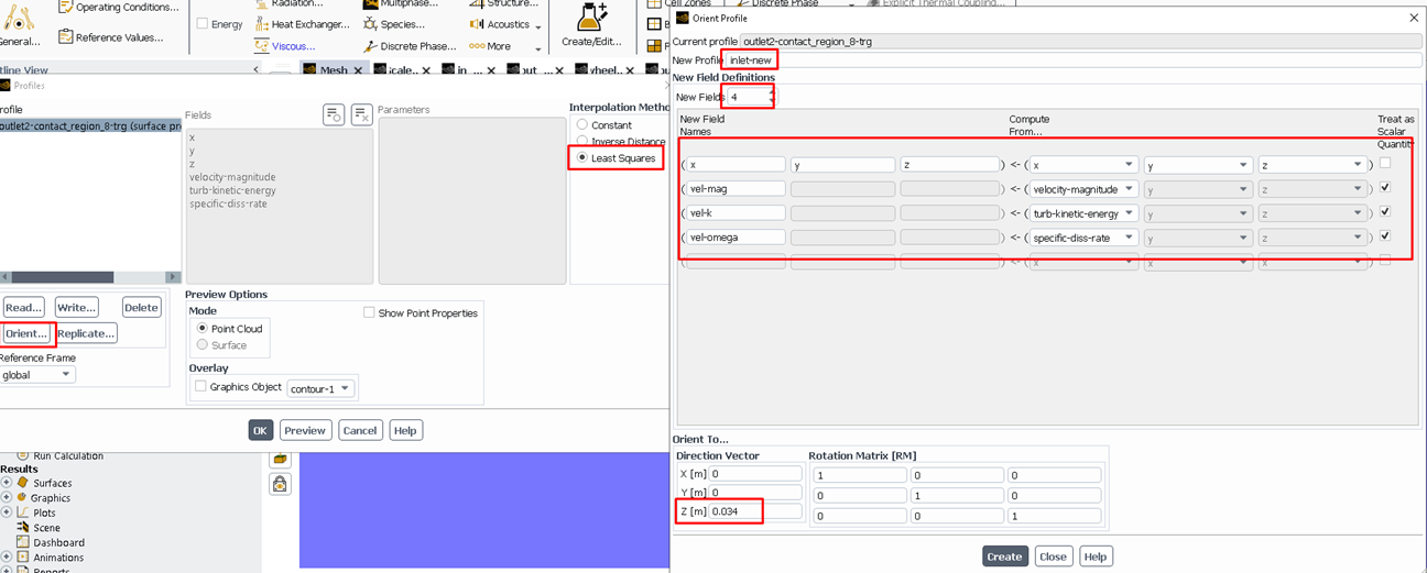
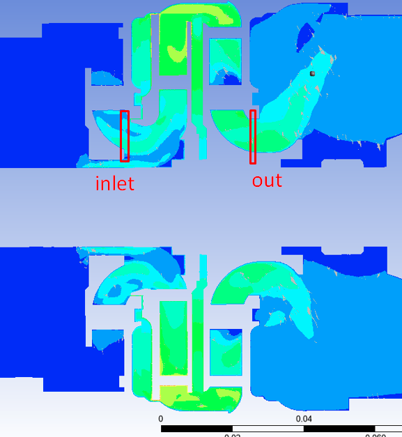
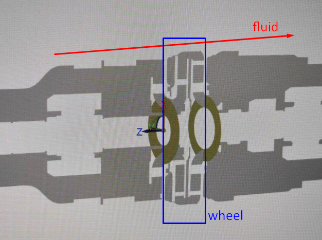
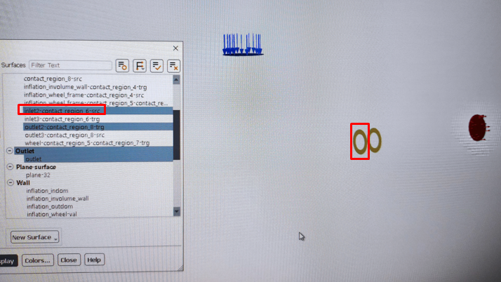
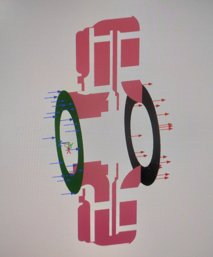
SubscriberHi all. I'm solving a centrifugal pump. I transfer the fluid velocity profile (magnitude velocity) from the end of the wheel to the beginning (I simulate that I have two wheels).Here's how I do it:1.I write to the out_wheel file and solve the problem.2.I am reading from the file out_wheel. And I already assign the file out_wheel1 to recording (so that I can then read out_wheel1, etc.).3. The entrance and exit from the wheel look like this:4.The input and output surfaces from the wheel are included in the interface section. So to enter the wheels, I had to change the type to INLET VELOCITY.There I select the magnitude velocity (it was connected from a readable file).5. I start a new calculation and see that the pressure has not increased much. Previously, the pressure was 10, now it is 13. At the same time, the flow rate at the pump inlet dropped from 3.7 to 2.1. The outlet pressure increased by only 0.3 atm.The pressure should have increased to 20 and the pressure would have increased by 1 atm.Maybe I did something wrong?Thank you. -
February 6, 2024 at 10:10 am
Rob
Forum ModeratorYou took the profile from one location and used it in a different location?
-
February 6, 2024 at 4:04 pm
javat33489
SubscriberYes Sir
-
-
February 6, 2024 at 4:19 pm
Rob
Forum ModeratorDid you alter the position data in the profile? The solver will interpolate from the file onto the surface you attach it to, if they don't align it's uncertain what values you'll be using.
-
February 6, 2024 at 4:24 pm
javat33489
SubscriberSir. What do you have in mind? Tell me more details please? I did only this: I read the data from one surface (output from the wheel) with velocity magnitudes and then assigned this file to be read on another surface (input of the wheel). Problems with the position of the surface in space according to XYZ coordinates?
-
-
February 6, 2024 at 4:27 pm
Rob
Forum Moderatorhttps://ansyshelp.ansys.com/account/Secured?returnurl=/Views/Secured/corp/v241/en/flu_ug/flu_ug_bcs_sec_prof.html You need to move the profile data too - otherwise it's seeing the x, y & z position of the original data.
-
February 6, 2024 at 4:50 pm
javat33489
SubscriberThank you sir, I understand. I thought about it! I'll try this and write later
-
February 7, 2024 at 4:34 pm
javat33489
SubscriberSir. Could you please post the function here if it exists? I am temporarily unable to follow your link.I also watched the video of ANSYS HOW TO:https://www.youtube.com/watch?v=-42b0tZufP8and I did everything the same. But it doesn't work.
-
-
February 7, 2024 at 4:59 pm
Rob
Forum ModeratorClick on Help in the solver and then paste the link into the browser. Otherwise, Profiles are covered in the User's Guide under Boundary Conditions.
Does the video cover that profiles have a position component so that you may need to manually correct that when moving from one model to another? Or make sure the two surface in the different models are in the same location.
-
February 8, 2024 at 7:11 pm
-
-
February 9, 2024 at 9:56 am
Rob
Forum ModeratorPlot the values you're using in the profile and compare the various contour plots. Do they look the same?
-
February 9, 2024 at 4:24 pm
-
-
February 9, 2024 at 4:32 pm
Rob
Forum ModeratorEach other, and use contours. You're checking you've got the data transfer right. Although I'm unsure how the flow on the upstream and downstream ends of a pump should compare, other than mass flow.
-
February 9, 2024 at 5:15 pm
javat33489
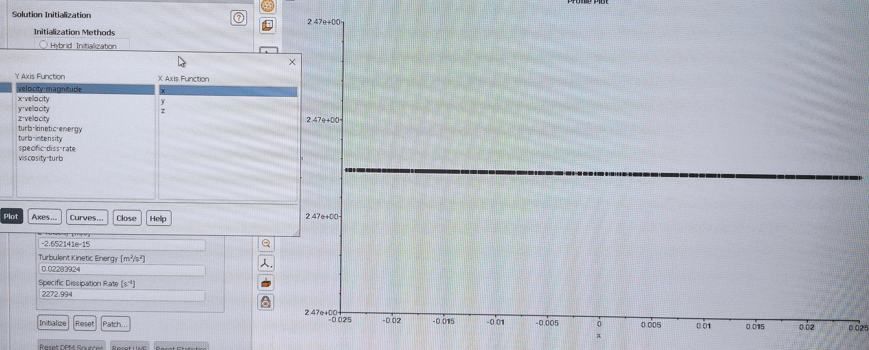
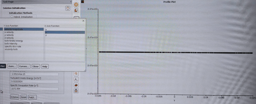
SubscriberI also tried creating a local coordinate system and linked the input profile to it. The result is the same. The consumption has increased by 1 (previously it was 10 - which coincides with the physical model). In reality, as for the physical model, the consumption should have been 20. With each wheel it increases by 10. This is what the speed profile looks like before using the profiles and transferring them:
-
-
February 12, 2024 at 11:18 am
Rob
Forum ModeratorYou're transferring the flow rate (velocity), what's different between the two profiles when added to the model?
-
February 12, 2024 at 6:00 pm
javat33489
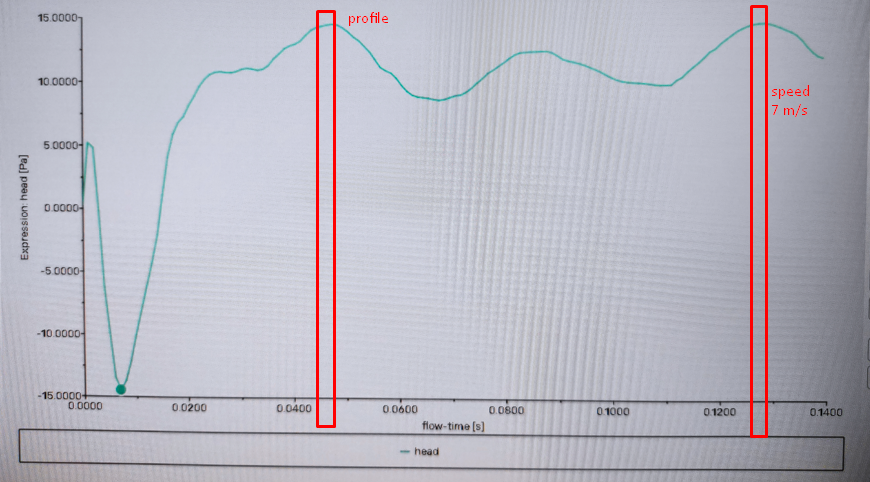
SubscriberSir, the profile on the right is the surface after the pump wheel, on the left is before the wheel. After the wheel, the flow speed almost doubles. My task is to transfer the speed after the wheel to the profile before the wheel so that the speed increases even more. So I want to simulate the second wheelI measured the speeds on the profiles, up to the wheel 4 m/s after the field 7 m/s.But no matter what I do, the speed does not increase, as if the profile is not working, but everything is done correctly.For the test, I simply set the speed to the wheel to 7 m/s, but only a jump occurred, then the speed returned to the same:I don't understand why this happens. It’s possible with profiles too, the system sees them but the speed does not change. At the same time, I also monitor the graphs when I read profiles, and the speed does not even change when connecting a profile.
-
-
February 13, 2024 at 9:43 am
Rob
Forum ModeratorA profile set on an external boundary will apply the speed in the profile. I'm a little lost as to what you're trying to get out of the model compared to what you're seeing. What does your Prof think of the modelling work so far?
-
February 13, 2024 at 4:32 pm
javat33489
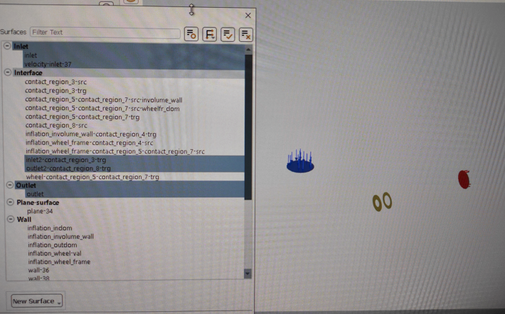
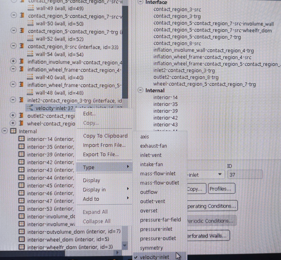
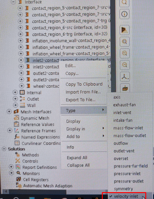
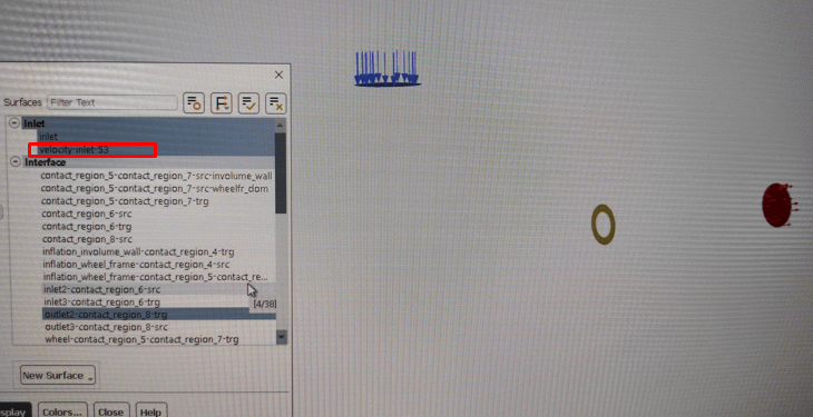
SubscriberThat's right. The profile after the wheel will have a speed greater than the profile before the wheel. I want to insert data after the wheel into the profile before the wheel to simulate the triple wheel of a centrifugal pump, there are 100 such wheels in total. I cannot load a model with 100 wheels, with only one wheel and then transfer flow data from the end of the wheel to the beginning simulating the next wheel and acceleration fluid in a centrifugal pump.Here are my observations. Whatever I do and the profile for which I set the speed gives only a small jerk in the flow graph, nothing happens on the speed graphs before and after the wheel.The profile from which I write information and into which I read are also contact between the grids and are located in the INTERFACE section in fluent.To assign profile reading to the profile before the wheel, I had to change its type like this:After which I assign the speed from the recorded profile.But here's what I noticed. When I turn on surfaces in fluent, the surface on which I enabled reading of the recorded profile does not see in the INLET section:But if you turn on the plane in the interface section, you can see it:So maybe the fluent doesn’t see this plane when calculating? Maybe it needs to be set some other way? Or create a new surface? Previously, I created this surface in mesh using the name selection command.PS.Even if I just set the speed to the surface up to the wheel manually, for example 15 m/s, there is only a jump for 1-2 iterations, after which all the graphs are restored to their previous values.
-
-
February 13, 2024 at 4:54 pm
Rob
Forum ModeratorAn interface zone is there to pass data from one mesh to one that is adjacent but not connected. A velocity inlet adds material from "outside" of the modelled domain.
Please talk to your supervisor about what you're doing.
-
February 14, 2024 at 5:05 pm
javat33489
SubscriberSir. I did a dozen more tests. I have to stop for now because I don’t know what else to come up with. The profile doesn't work.This time I left only the centrifugal pump wheel. It has an input and an output:I write data from the output and then read it from the input. But the profile still doesn't work. There is a jump in the graphs, but after a few iterations everything returns back, as if the profile is not connected. But I noticed that the speed graph dropped by a third and did not rise.I also did a test, I set the input speed directly to twice as high. There was a sharp jump, but then everything came back, as if I had not increased the speed.Very strange behavior. After the wheel, the flow speed increases almost double and if you set this to the wheel input, the speed should increase even more. Could the problem be that the flow rate is set at the output?
-
-
February 15, 2024 at 9:05 am
Rob
Forum ModeratorIf you set the input speed to be double that it was previously and it's then dropping back, you've got something else set in the model. The boundary conditions are what tell Fluent what is entering the domain. However, given the number of threads, and confusion over profiles at interface surfaces I don't know what you've set as compared to what should be set. Hence talking to your Prof
-
February 19, 2024 at 6:43 pm
javat33489
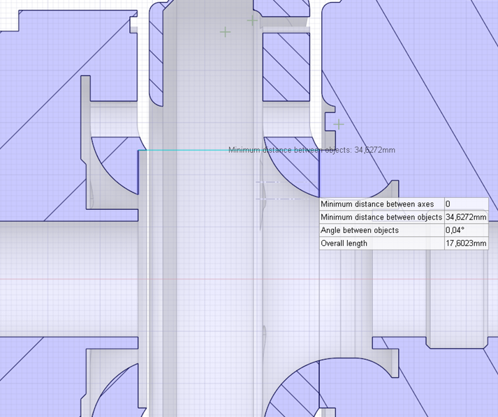
SubscriberSo. Let's summarize what I did and how it worked.I reduced the geometry to just a wheel. The geometry now consists of 3 objects: the wheel itself, the inlet boss, and the housing around the wheel, all of which are extracted water. The wheel rotates 3000 rpm. The entrance boss in front of the wheel is the same in area as the exit. The task is to record the fluid profile from the output and transfer it to the input to simulate the second wheel in a centrifugal pump. As a result, I should see an increase in pressure at the exit of the wheel by approximately half as a result of an increase in the speed transmitted by the wheel. Boundary conditions: pressure at the inlet, flow at the outlet.The geometry itself is debugged and the calculation on one pump wheel coincides with the physical tests.I tried two approaches, this is writing the profile and reading it to the input using an offset (orientation). And also the creation of a second coordinate plane at the input and indicated to read the profile there. The result is the same and both of them did not work.In doing so, I tried different k-omega and k-epsilon turbulence models, and I also tried different DROP, SIMPLE, and SIMPLEC methods. I also tried using hybrid and standard initialization.During the calculation, I tracked speed, pressure, flow, inlet and outlet on graphs. But when using the profile, the pressure did not increase but returned to normal as before, and the inlet pressure completely dropped below 1 atmosphere.For the test, I also tried to set the increased input speed manually, through the input boundary conditions. At first there was a surge in pressure, but then everything returned to normal.No matter what I did, the pressure did not increase.
-
-
February 20, 2024 at 12:07 pm
Rob
Forum ModeratorOK, so on the second section you use a profile, which has data from the outlet end of the first compressor section. What are you setting on that boundary? Ie velocity, mass flow or pressure? You then initialise the system. I'm not sure why pressure would spike and then drop, unless you've not set something in the model.
What has your project supervisor said about this?
-
February 21, 2024 at 1:55 am
javat33489
Subscriber>> Ie velocity, mass flow or pressure?
From the output profile I record the velocity magnitude k and omega. Then at the input I change the pressure to the speed and set the previously recorded data (from the output).
>>I'm not sure why pressure would spike and then drop, unless you've not set something in the model.
No, I didn't change the model and it works fine.
-
-
February 21, 2024 at 9:36 am
Rob
Forum ModeratorOK, so there's no longer a problem?
-
February 21, 2024 at 4:44 pm
javat33489
SubscriberSir. I noticed something.
Previously, when I read a recorded profile and set its data to the input, I did not carry out a new initialization but immediately launched it for calculation.
Now, after setting up reading the output profile and setting its data to the input, I carried out the initialization and received the following error:
-
-
February 21, 2024 at 5:05 pm
Rob
Forum ModeratorCheck what you set, and also whether the problem is a one off or is repeatable. There may be something wrong with the profile format if you've written, editted and read into Fluent.
-
February 21, 2024 at 5:27 pm
javat33489
SubscriberI restarted fluent several times. The error does not go away. Which profile could be the problem? There is a simple setup and everything is fine with the model.
-
-
February 22, 2024 at 9:42 am
Rob
Forum ModeratorThe solver thinks there is some data missing, or that something is zero that shouldn't be.
-
March 17, 2024 at 7:09 pm
javat33489
SubscriberYes, sir. But I'm doing everything right. Could you give me any recommendations on what else needs to be checked?
-
-
March 18, 2024 at 10:14 am
Rob
Forum ModeratorCheck the domain scale (ribbon menu). Then start at the top of the tree (left hand menu in Fluent) and go through every setting/option. Do they tie in with the settings you wrote down in the model plan? If yes, move on, if not correct the error or correct the plan. I don't know what's gone wrong, and am not allowed to get the case to have a look: hence I suggest talking to your supervisor/Prof to get a second pair of eyes on the model.
-
- The topic ‘Problem when writing/reading a profile in Fluent’ is closed to new replies.


-
4678
-
1565
-
1386
-
1242
-
1021

© 2025 Copyright ANSYS, Inc. All rights reserved.

