-
-
May 2, 2024 at 11:07 am
abhishek.srivastava2
SubscriberHello everyone,
I am simulating a pipe flow (air) where the air enters the pipe through holes drilled at several locations. I am using the BC of pressure inlet at holes (0 Pa) and pressure outlet at the end of the pipe (suction from fan, given value). I want to check the airflow rate and pressure drop at each hole. For now, my model is able to get the correct flow rate and pressure for the holes far frompipe suction but i am getting error (high pressure) in the first 2 holes which are closer to the pipe suction. Could you please guide what could be wrong? and any recommnedations in the design. I am using k-omega SST with production limiter. Please let me know if any mpore info is needed.Â
 Â
Â
-
May 2, 2024 at 12:47 pm
Rob
Forum ModeratorWhat does the convergence look like? How is the flow field? How many cells across the ports and pipe diameter?Â
-
May 2, 2024 at 1:17 pm
abhishek.srivastava2
Subscriberpipe dia = 21mm
hole size = 5 - 8.5mm at equal distance
around 1.7M cells with inflation on the pipe wall (stair step mesh), proximity sizing for each hole and hole enclosure, minimum orthogonal quality 0.2.Â
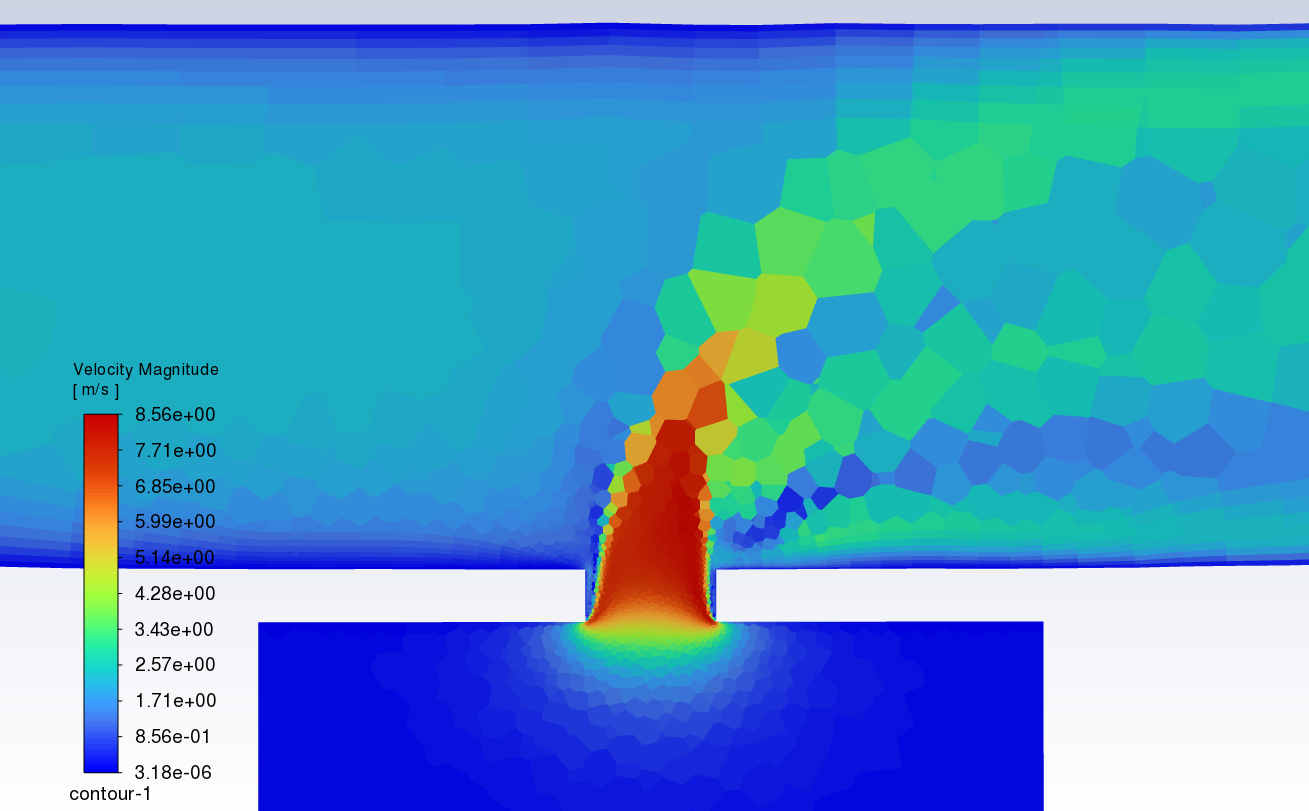
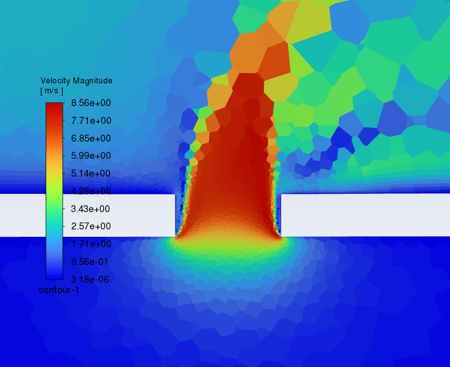
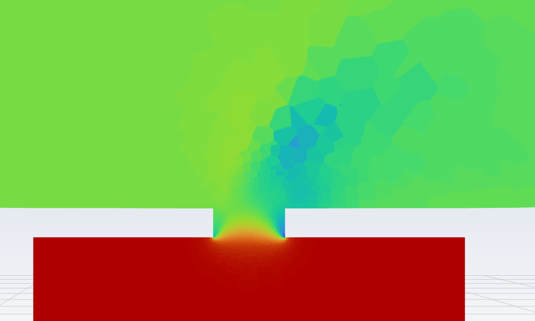
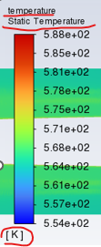
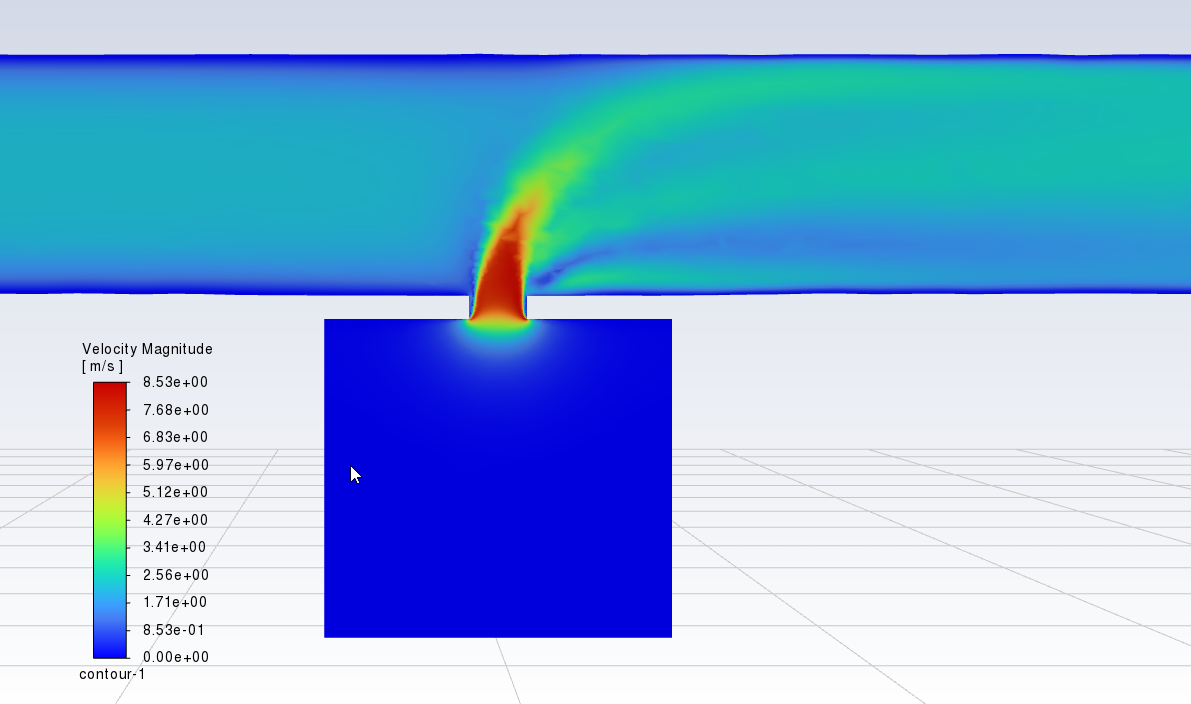
velocity profile (target average velocity should be 6.5 m/s)
Â
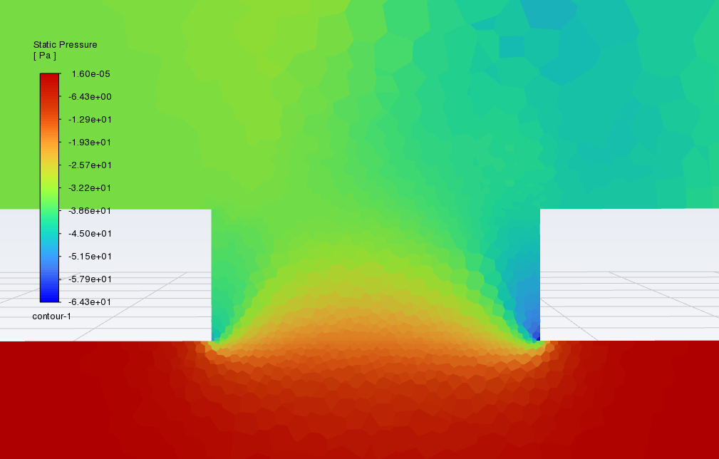
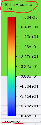
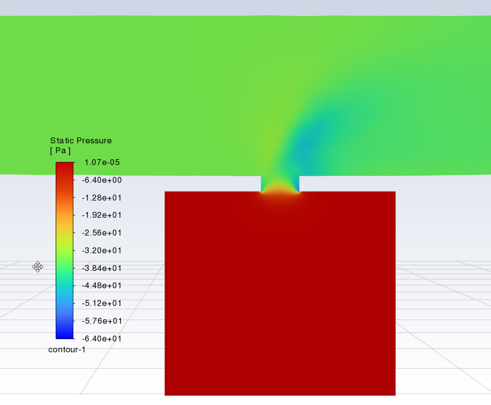
pressure: (target pressure drop 32 Pa, i am getting 36Pa)
Do you think i should enable transition model as well (I think its more apt for moving surfaces which ia not my case) to reduce the pressure drop?Â
-
May 2, 2024 at 2:28 pm
Rob
Forum ModeratorAnd the mesh resolution is retained along the pipe? I doubt transition models will do much for the solution, but the flow field in the velocity contour looks a little odd, please replot with node values off.Â
Why are you expecting 32Pa pressure drop in the domain?Â
-
May 2, 2024 at 3:05 pm
abhishek.srivastava2
Subscriberyes, the mesh resolution for me is good along the pipe. No high transitions anywhere. I am doing validation study of the flow rate and pressure drop for all holes. For all the other 4 holes the pressure drop is more or less what i want but the first 2 holes have higher deviation. I don't think even refining mesh further will solve the problem. I can create a boi around the hole, maybe it can resolve better?
Â
Â
-
May 2, 2024 at 3:19 pm
Rob
Forum ModeratorSome more resolution may help. Remember there's mesh refinement (adaption) in the solver. The hole looks OK, it's the jet that's less well resolved.Â
-
May 2, 2024 at 3:43 pm
abhishek.srivastava2
SubscriberOkay, I'll try it and get back tomorrow. Thank you
-
May 4, 2024 at 11:49 pm
abhishek.srivastava2
SubscriberEven refining the mesh is not solving the problem. I am unable to get the reason for this additional loss in hole next to the pipe exhaust? ideally it should be frictional losses but even after refining the mesh and giving inflation even on the hole walls is not resolving the error. I am also working on doing some hand calculation for the losses through hole. If you have any reference document please let me know.Â
-
May 9, 2024 at 11:21 am
Dato
SubscriberExcuse me, Could you tell me what version of Fluent are you using?
-
-
May 7, 2024 at 9:54 am
Rob
Forum ModeratorLoss through a hole should be covered in most fluids text books. However, most of those assume discharge into free space whereas you have a cross flow. If you know the exit flow try removing the fan and setting a negative velocity as that can be more stable. In your current set up you have pressure in, pressure out and a fan, so all external boundaries will adjust mass flow to meet the pressure value, and the fan will alter the pressure jump based on mass flow: that's not necessarily going to converge well.Â
-
May 8, 2024 at 3:01 am
Dato
SubscriberHi Rob,
I have a question about the colormap legend of graphics. I'm using 2022R2 and legend pattern is shown below which is differnt from the ones in this discussion. Contour and variable name is above the legend and unit is located under the legend.Â
I want to set variable name and unit at same location without contour name displayed like this. How can I do it ?
Regards.
-
-
May 8, 2024 at 10:27 am
Rob
Forum ModeratorYou can check the options in the contour panel and View tab but some of the legend set up is hard coded. It's also changed several times over the last few releases as Fluent's graphics have been upgraded.Â
-
May 9, 2024 at 11:35 am
Dato
SubscriberI have already tried these panel but the position of unit cannot be changed still. Same situation in cfd-post. ????
-
-
- The topic ‘Pressure drop through a hole in a pipe’ is closed to new replies.
- How do I get my hands on Ansys Rocky DEM
- Unburnt Hydrocarbons contour in ANSYS FORTE for sector mesh
- convergence issue for transonic flow
- Facing trouble regarding setting up boundary conditions for SOEC Modeling
- Point exception in erosion calculation
- Errors with multi-connected bodies using AQWA
- Script Error Ansys
-
2532
-
933
-
787
-
599
-
591
© 2025 Copyright ANSYS, Inc. All rights reserved.