-
-
July 3, 2023 at 11:08 am
pv00170
SubscriberI am analysing hydraulic pressures on submerged steel girders, and then I am performing FE analysis to see their structural behaviour using ANSYS Structural.
When I perform CFD, I get the pressures on the girder's surface.
The thing is that in ANSYS Structural, I want to change these girders to shells rather than solids (as used in CFD). This is because the girders are really thin, and they generate problems when doing a structural analysis.
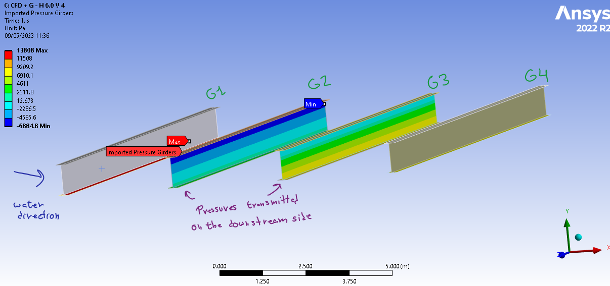
Problems appear when I want to import CFD pressures to those shells, as only one side of the shell "imports pressures," and therefore the ones on the other side of the solid are ignored. The correct load to be applied to the shell elements is the pressure difference on both sides of the solid. (see images)
My question is: How can I transfer and obtain this pressure difference on those sides (not force!) ?
The same question has been raised as a Structural topic, but I think the solution lies in managing CFD results.
/forum/forums/topic/bridge-bearing-modelling-in-static-structural/
-
July 5, 2023 at 10:38 am
Aniket
Forum ModeratorHow are you importing pressures? Are you exporting csv files from CFD and then bringing in the data to Structural using external Data
OR directly coupling CFD to Structural?
If the former, you can use a multiplier of (-1) for pressure from one side and then map two csv files on same surface, I believe this should add two different pressures and give you the difference.
-Aniket
-
July 5, 2023 at 12:29 pm
pv00170
SubscriberI am importing csv files which has:
nodenumber, x-coordinate, y-coordinate, pressure
1, 3.120017000E+01, 4.856500000E+00, 4.426002436E+03
2, 3.123076680E+01, 4.856500000E+00,-1.081903081E+03
3, 3.126131470E+01, 4.856500000E+00, 6.745413607E+02Problem is that if I change the girder to a shell, it might change from a 3D to 2D. Therefore, x-possition changes.
About the (-1), I think its a really good idea. Just wondering if as possition changes, it would be propertly transfered.
-
July 5, 2023 at 6:02 pm
Aniket
Forum Moderatorthe difference in the x coordinate can be taken care of by the mapping process. You may not need to change the x coordinates manually. Try without it and see if that helps.
-Aniket
-
-
-
- The topic ‘Pressure difference of two faces’ is closed to new replies.


-
4838
-
1587
-
1386
-
1242
-
1021

© 2026 Copyright ANSYS, Inc. All rights reserved.


