-
-
February 12, 2022 at 8:48 pm
OROI
SubscriberHi
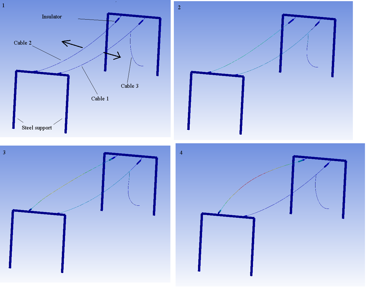
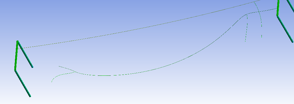
I'm simulating power line cable behavior after short circuit. At this point problem is that if i add that vertical cable 3 to model and connect i to cable1 ( fixed body-body, cable3 vertex to cable1 edge) cable 1 becomes too stiff. Load force for cable 1 and cable 2 are same, but opposite directions. Model itself is basic beam element model. Cable 1 and 2 are about 40 m long and material is copper and diameter is 23 mm. Cable 3 is same material than other cables, lower end is fixed to ground. Is the problem that joint connection between cable 1 and 3 ? How to make cable 1 behave more flexible if there is that vertical cable 3 connected.
Here is some still pictures
February 12, 2022 at 9:56 pmRameez_ul_Haq
Subscribercable 1 has to become too stiff because you are restricting the motion of the cable 1 (along X axis) by connecting cable 3 to the ground. So you are adding stiffness to cable 1 now because now it has a support somwhere along its length (to be exact, at the location where you are connecting cable 1 to cable 3). So I don't think there is any problem with the results.
You might not be seeing what you expected, but that perhaps is because you didn't model it correctly which would give you the desired results.
February 13, 2022 at 12:46 amOROI
SubscriberYes i understand that the cable 3 adds stiffness, but it seems that other end of cable 1 has same amount deformation than that the end of cable 1, which has that vertical cable 3 connected. I think it should have more deformation along Y axis at that opposite end of cable 1. I attached short video of it.
February 13, 2022 at 10:26 amRameez_ul_Haq
Subscriber,because you are also connecting the other end of cable 1 to the steel support, so this support is adding stiffness to the cable 1 at that end as well. Isn't it? Or I still couldn't understand why is that a problem for you?
February 13, 2022 at 1:25 pmOROI
SubscriberThe problem is that the cable 1 should not be that equal stiff all of its length. It feels like the vertical cable stiffness affects in every point of that cable 1. It kind of should only affect on that connection point, but i don't know how to do that, because i can only select cable 1 edge and cable 3 end vertex point for the joint.
I made cable 3 very rigid, i attached video where you can see that the cable 1 is very stiff and cable 1 pivots around the cable 3 end vertex point.
February 13, 2022 at 5:17 pmRameez_ul_Haq
SubscriberMaybe could help you with this here. I still think the behavior of the cable 1 should be like what you see as results in ANSYS Transient Module.
Also, share your model as an Archieve file here, if possible.
February 13, 2022 at 6:36 pmpeteroznewman
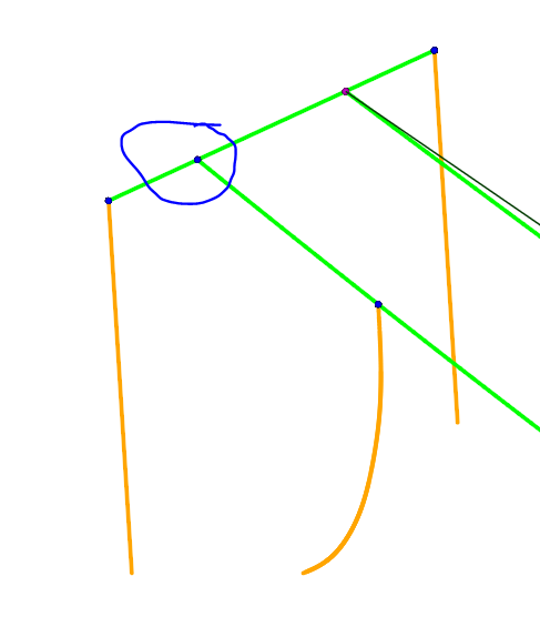
SubscriberDon't do this: fixed body-body, cable3 vertex to cable1 edge
Instead, add a vertex to cable 1 and do this: fixed body-body, cable3 vertex to cable1 vertex
February 13, 2022 at 6:58 pmFebruary 13, 2022 at 9:40 pmpeteroznewman
SubscriberYou have to replace one long line with two lines that meet where you want a vertex. You can use Shared Topology to create a single node that the two line segments will share.
February 13, 2022 at 10:33 pmOROI
Subscriber
I put it like this and now i can select every vertex easily.
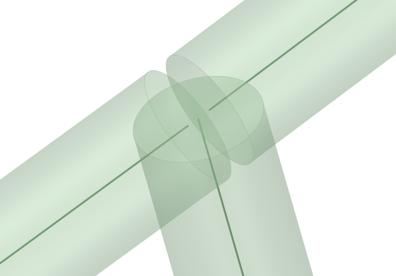 But now i got error if gravity is active, if gravity is suppressed it will solve without error.
" error: The solver engine was unable to converge on a solution for the nonlinear problem as constrained.Please see the Troubleshooting section of the Help System for more information."
*** ERROR ***CP =38.797TIME= 00:28:38
Solution not converged at time 1.E-04 (load step 1 substep 1).
Run terminated.
*** WARNING ***CP =38.797TIME= 00:28:38
The unconverged solution (identified as time 0.1 substep 999999) is
output for analysis debug purposes.Results should not be used for
any other purpose.
What could be the problem?
February 14, 2022 at 1:03 ampeteroznewman
SubscriberThe solver needs some initial strain put into the cable to create an initial tension for the force of gravity to work against. See some of the discussions on this site.
https://www.google.com/search?q=site%3Aforum.ansys.com+INISTATE+cable+gravity
February 14, 2022 at 7:42 pmOROI
SubscriberI added these APDL commands to every cable beam:
stress=150/415
INISTATE,SET,CSYS,-2
INISTATE,SET,DTYP,STRE
INISTATE,DEFINE,,,,,stress
It solves if force is 150 N, i tried lower and higher value , but then i get error. Is this initial tension how important in this kind of simulation, so is it ok if i use this 150 N? My goal is measure what kind of forces power line cable movement can cause to insulators and steel support.
February 14, 2022 at 8:24 pmpeteroznewman
SubscriberAll you need is for it to solve. It is called Initial State, which means that is only an initial value and as the solution iterates, the correct value of stress will be found that satisfies equilibrium.
I assume you have Large Deflection turned On.
February 14, 2022 at 9:05 pmFebruary 15, 2022 at 11:16 pmOROI
SubscriberI can use directional deformation X and Y values to make that kind of plot.
February 16, 2022 at 7:20 pmOROI
SubscriberI tried to change little bit steel support wall thickness and now i get same kind of error like before i have those APDL commands in cable beams. Should i add that same initial tension command to rest of the model beams? How i can know working stress value for that APLD command input, without testing it many times?
February 16, 2022 at 9:22 pmpeteroznewman
SubscriberIt might help convergence if all the cables start with some value of initial stress. Use a cable calculator
https://www.engineeringtoolbox.com/cable-loads-d_1816.html
to compute the tension in a cable hanging under gravity. Once you know the tension, you can compute the stress by dividing by the cross-sectional area.
February 17, 2022 at 6:31 pmOROI
Subscriber
I made the model even more simplified and now it will not solve anymore. I tried different initial stress values but getting error. If i turn off Large Deflection then it solves, but results are useless. Here is the model attached. It would be nice, if you have time to see what is wrong.
February 17, 2022 at 7:27 pmpeteroznewman
SubscriberI let the first second ramp acceleration up from 0 to 1g with time integration turned off and that had no problem converging.
Then I added 10 seconds of transient with time integration on, and that had no problems. You don't need 10 seconds, maybe 1 extra second. I also added Damping to the Analysis Settings. You must include Damping.
All that was with the Force suppressed.
Add 2 seconds to the time column and let the first 2 seconds have zero force, then start the force after 2 seconds for the length of the transient.
February 17, 2022 at 9:49 pmOROI
Subscriber
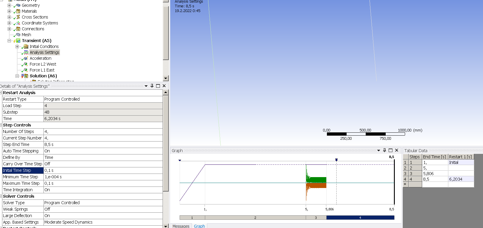
Thanks, that helped over the initial stage. Now problem is at step 4. It solves without force, but if force is active then i get error at time about 6.2 seconds. I tried to adjust step 4 time stepping, but it did not solve the error.
February 18, 2022 at 9:02 pmOROI
Subscriber
I tried use 1/4 force and then it solves, but if force is higher then i get error. I made horizontal cables little bit shorter and also stiffened steel supports. After those changes it solves with full force. Do you have some ideas why it can't solve if the model is more flexible. The point when error happens is about when the cable drop force is high at first time and this is after when load force is no more active.
February 18, 2022 at 9:57 pmpeteroznewman
SubscriberWhat is the error?
February 18, 2022 at 10:35 pmOROI
SubscriberHere is error log:
*** WARNING ***CP =0.967TIME= 00:17:50
Element shape checking is currently inactive.Issue SHPP,ON or
SHPP,WARN to reactivate, if desired.
*** WARNING ***CP =0.967TIME= 00:17:50
Material number 28 (used by element 802) should normally have at least
one MP or one TB type command associated with it.Output of energy by
material may not be available.
*** WARNING ***CP =0.967TIME= 00:17:50
No constraints have been defined using the D command.
*** WARNING ***CP =1.482TIME= 00:17:50
Pivoting has been activated for the Distributed Sparse Matrix Solver .
The memory required may greatly exceed the predicted amount.In that
event, use the DSPOPTION command to change the memory mode and/or
memory size used by the Distributed Sparse Matrix Solver.
*** WARNING ***CP =15.959TIME= 00:18:05
Material number 28 (used by element 802) should normally have at least
one MP or one TB type command associated with it.Output of energy by
material may not be available.
*** WARNING ***CP =70.793TIME= 00:19:00
Material number 28 (used by element 802) should normally have at least
one MP or one TB type command associated with it.Output of energy by
material may not be available.
*** WARNING ***CP =667.793TIME= 00:29:20
Material number 28 (used by element 802) should normally have at least
one MP or one TB type command associated with it.Output of energy by
material may not be available.
*** ERROR ***CP =828.303TIME= 00:32:06
Solution not converged at time 6.20348279 (load step 4 substep 49).
Run terminated.
*** WARNING ***CP =828.303TIME= 00:32:06
The unconverged solution (identified as time 8.5 substep 999999) is
output for analysis debug purposes.Results should not be used for
any other purpose.
February 18, 2022 at 10:44 pmpeteroznewman
SubscriberPlease show the Analysis Settings. Do you allow for Auto Time Stepping? What is the Minimum Time Step? What was the time step when the error occurred?
February 18, 2022 at 10:47 pmFebruary 18, 2022 at 10:55 pmpeteroznewman
SubscriberWhat happens if you set the Minimum Time Step to be 1e-6?
February 18, 2022 at 11:20 pmOROI
SubscriberSame kind of error:
*** ERROR ***CP =1039.965TIME= 01:17:44
Solution not converged at time 6.2038866 (load step 4 substep 83).
Run terminated.
February 19, 2022 at 12:44 amFebruary 19, 2022 at 11:15 amOROI
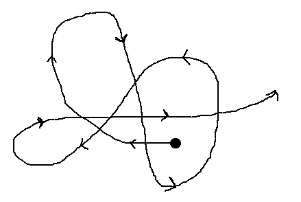
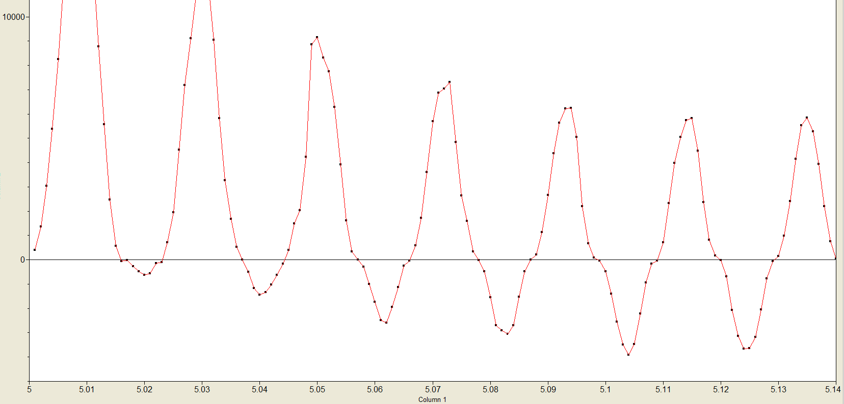
SubscriberThe force data is correct because the current has DC offset and 180 degrees phase shift between lines, when line-line short circuit happens. So that causes electromagnetic force look like this and another cable force sign is opposite. Also i made current data points from picture so that's why it is not that sinusoidal looking.
To me is odd that why initial stage changes affects to step 4 simulation error, because earlier with instant earth gravity and 150/415 stress value setting it was working with full force without problem, except that i can't change steel support more stiff, but i was able to add three vertical cables to model.
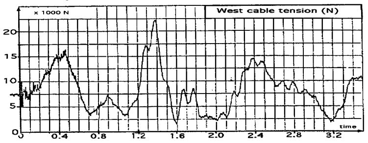
Here is picture, with that old earth gravity setup with added vertical cables. Cable drops between 1.2-1.6 seconds and causes quite high force to horizontal cable fixation point of steel support. This is the problematic point in new initial stage setup. I'm trying to match my simulation results to real world experimental results. So that's why i need to adjust the model. In my model the cable tension is about 2kN too low compared to experimental results and also cable sag is higher in my model.
 Here is experimental results of that same measuring point:
February 19, 2022 at 3:45 pmpeteroznewman
SubscriberOkay, I've changed my opinion. I see that due to the 50 Hz AC current, the force direction reverses at a 100 Hz frequency.
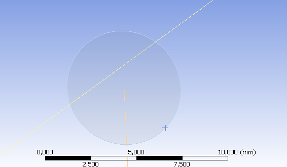
I went into SpaceClaim and changed the tolerance on the Share to 10 mm from 0.2 mm. That allowed all locations to merge. I deleted all Joints. I used Fixed Supports on all the Ground points. I changed the Analysis Settings to a cleaner set of steps. I changed the Damping after I obtained the first natural frequency from the Modal analysis. It now simulates to the end.
If the cable tension is too low, there are two ways you could increase it. One way is to add mass to the cables. One simple way to do that is to change the density of the material. Do you know the correct mass per unit length of the cable with all the insulation on it? Another way to increase cable tension is to draw a larger radius in SpaceClaim and make the cable length shorter.
How do you measure cable sag and what is the target value. Drawing a larger radius in SpaceClaim will also reduce cable sag, so it sounds like you need to do that.
February 20, 2022 at 12:48 pmOROI
Subscriber
Great thanks, can you show me where is that share tolerance option and that damping. Is that damping change causing that cables are acting more smoothly and does not rise enough high to drop back and causing high dropping force? Cable mass is 2,9 kg/m and at the end of horizontal cable is insulator, which is 1,54 m / 52 kg. Cable sag should be 950 mm, i draw the cable line to that sag point already so when gravity is active i can see that sag is clearly too much. Do you know why i can't find that acceleration value in insert list?
February 20, 2022 at 3:07 pmpeteroznewman
Subscriber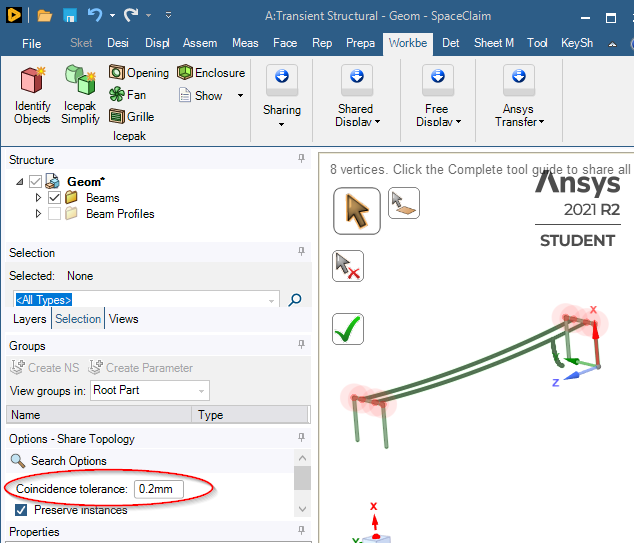
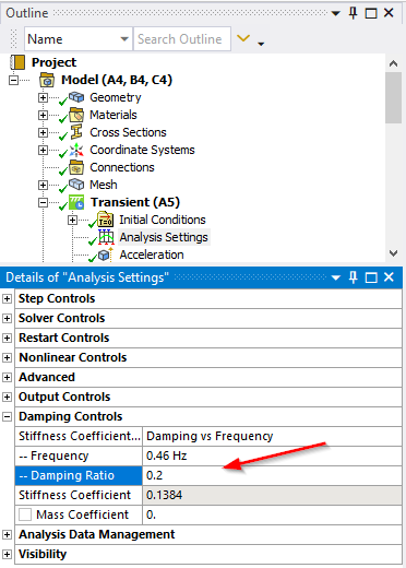 If the cable mass should be 2.9 kg/m you have to adjust the material density. The long cable you have is 40 m long and weighs 126.4 kg = 3.15 kg/m. Multiply the density of the material by 2.9/3.15 = 0.919 to get an adjusted density. However, there two other important parameters of the beam model of the cable. One is the axial stiffness of the cable. Cable vendors often list the stretch of their cable. For example, applying 1,000 N to the end of a 1 m long cable will create a stretch of 1.23 mm for example (just making up some numbers). That value will affect the sag of your cable. Another important parameter is the bending stiffness of the cable. You should vary the Young's Modulus of the material, and the Diameter of the cross-section until both the axial stiffness and the bending stiffness match measured cable properties.
Reducing density will cause less cable tension, so you really need to draw a larger radius in SpaceClaim to get the cable tension correct. However, you also need to set the axial stiffness to the correct value before you try to redraw the radius of curvature in SpaceClaim since this will interact with the density to deliver a resultant sag.
You have to type in an acceleration value, it doesn't drop down.
February 22, 2022 at 6:15 pmFebruary 22, 2022 at 9:00 pmpeteroznewman
SubscriberIn SpaceClaim, on the Workbench tab, click Unshare, then click the Share button and type in a 20 mm tolerance value instead of the 0.2 mm tolerance. Send me a screenshot of these points. They should be highlighted with glowing red clouds around each point.
In Mechanical there are ways to turn on the Node ID numbers. I have never needed that in Mechanical, but if you learn how to do that, you will see if there is a single node or duplicate nodes.
If there were duplicate nodes, you could do a Node Merge in Mechanical to join the three beam elements to the same node.
February 23, 2022 at 8:11 pmOROI
SubscriberI made new shorter cable beam and shared it and now it's connected together.
Viewing 34 reply threads- The topic ‘Power line cable behavior simulation’ is closed to new replies.
Innovation SpaceTrending discussionsTop Contributors-
4783
-
1565
-
1386
-
1242
-
1021
Top Rated Tags© 2026 Copyright ANSYS, Inc. All rights reserved.
Ansys does not support the usage of unauthorized Ansys software. Please visit www.ansys.com to obtain an official distribution.
-
The Ansys Learning Forum is a public forum. You are prohibited from providing (i) information that is confidential to You, your employer, or any third party, (ii) Personal Data or individually identifiable health information, (iii) any information that is U.S. Government Classified, Controlled Unclassified Information, International Traffic in Arms Regulators (ITAR) or Export Administration Regulators (EAR) controlled or otherwise have been determined by the United States Government or by a foreign government to require protection against unauthorized disclosure for reasons of national security, or (iv) topics or information restricted by the People's Republic of China data protection and privacy laws.

