-
-
July 3, 2023 at 11:42 pm
Amir
SubscriberWhen modeling a domain as porous zone we need to enter the values for viscous and inertial resistance, what are the ways one can calculate these values?
I am aware of using experimental pressure drop vs velocity data, in case experimental data are not available, is there any other approach to get these values?
And are these values unique for each pair of porous material and the flowing fluid? In other words, if we were to calculate the values experimentaly, would we have to do the experiment for each type of porous material and flow?
Thanks.
-
July 4, 2023 at 7:57 am
Rob
Forum ModeratorIf you look through the manual section there are a few ways to find the coefficients. You'll also note the fluid density and viscosity feature in the equation: if you do the maths what does that tell you?
Another option is to build a sub model of part of the whatever it is you want to model as a porous block. Run the CFD model in exactly the same way as you would the experiment and take that data to get the coefficients. We've done that for grates, chemical plant and the like.
-
July 5, 2023 at 7:17 pm
Amir
SubscriberThanks Rob I understand.
The material I am trying to model as porous zone is soil. You think trying to actually make a very small domain of that would be possible/realistic?
-
-
July 6, 2023 at 7:44 am
Rob
Forum ModeratorWe've modelled enough things over the years to be fairly confident that just about anything can be modelled, although whether that's a good idea is something we're less confident of. I'm the one who spent 3-4 weeks building a lung mesh off an MRI because it seemed like a good idea at the time..... Turns out it was a good idea, and the technology means it'll take a lot less time now.
Soil is complicated, and resistance coefficients will depend on what sort of soil you have. The Ergun Equation approach might be a good starting point. Otherwise, you're going to need a friendly geologist with a lab.
-
July 11, 2023 at 11:43 pm
Amir
SubscriberThank you Rob,
I started with Ergun's equation and considered soil to be a mix of Sand, Silt and Clay spherical particles. By that I calculated coefficients to start with.
For viscous resistance the values are 2e+9 and for inertial rsistance are 4e+4.
For Non-equilibrium Thermal model and by taking weighted average for components, I calculated Interfacial Area Density as around 6e+5 [1/m].
Do you think these values can be used to start with? (I am asking to just make sure they are not out of scope and currently do not expect them to be accurate.)
And also about Heat Transfer Coefficient under Non-equilibrium tab, do you have any comment/advice on how I could calculate that as well?
-
-
July 12, 2023 at 8:52 am
Rob
Forum ModeratorThey're not silly high, but I can't comment as to whether they're correct for your application. That's for you to check as I've not done (and am not doing) the model.
HTC from fluid to solid in soil, I'd look for a correlation similar to the Ergun equation. Or if there are any papers on packed bed reactors. Check how the solid interacts with the fluid walls (it doesn't) before deciding if you should use it.
-
July 28, 2023 at 5:13 pm
Amir
SubscriberThank you Rob.
I am having an issue and I would appreciate your comment on that.
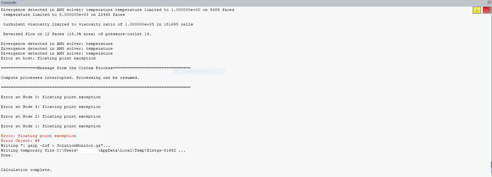
Initially I ran the simulation with mentioned values and solution got converged, but after making some corrections and running the same case (same mesh) with new porous zone values solution is diverging and gives “floating point exception error”.
For the following values:
Viscous Resistance: 2e+9
Inertial Resistance: 4e+4
Interfacial Area Density: 6e+5 (1/m)
Fluid Porosity: 0.48 Solution got converged with 0.001s as time step size.
For the current values:
Viscous Resistance: 5e+9
Inertial Resistance: 1e+5
Interfacial Area Density: 7e+5 (1/m)
Fluid Porosity: 0.25 Solution is diverging with the attached errors :
I tried reducing time step size to 1e-6s, but no chance. EWF is on as well( but not in the porous zone, if that is relavant)
Could it simply be low mesh quality or something else?
-
August 15, 2023 at 10:10 pm
Amir
SubscriberSorry Rob what do you mean by ” Check how the solid interacts with the fluid walls (it doesn’t) before deciding if you should use it. “?
When the fluid passes through porous medium, wont be any thermal interaction between them?
Lets say there is an enclosure filled with solid spherical particles and some space is empty and open for fluid to pass, when fluid (in this case a gas with higher temp than spheres) passes through, they exchange heat right? Is this Heat Transfer Coefficient for that interaction? or I am getting something wrong about porous zone modeling?
I found a paper on heat transfer in packed beds which addresses Furnas equation in Kitaev's book (attached image), but seems they are mostly based on experimental data for limited material and flow velocities and I am in doubt if they would be applicable for modelling soil as packed bed.
Thanks
-
August 16, 2023 at 8:52 am
Rob
Forum ModeratorFluid will pass heat to the porous zone with the non-equilibrium model. However, the casing wall (fluid boundary) is not the same as the wall that's generated in the same location when Fluent add the overlay mesh for the non-equilibrium porous model. The two walls have no thermal links in the solver.
Similarly the wall film models will see walls only (no porous jumps) and will see the fluid bounding wall and not the wall bounding the porous-solid zone.
-
August 16, 2023 at 10:55 am
Amir
SubscriberThanks, very informative.
I turned EWF off since liquid water presence would require multiphase model which wont be compatible with non-equilibrium thermal. But is it possible in way (like system coupling?) to include liquid formation and heat transfer through the wall as well?
-
August 16, 2023 at 11:07 am
Rob
Forum ModeratorHeat transfer could be worked out using UDFs, but it's not simple and I can't go into any details as it's beyond what I can cover on here. System Coupling can handle two Fluent models (with some work) but I'm less sure about coincident Fluent mesh zones as you have here.
-
-
-
July 31, 2023 at 8:25 am
Rob
Forum ModeratorThe changes are likely to alter the domain temperature field. That could be something in the porous zone, but it depends what you're doing with the film model. With a complex system you either need to know what's going to happen before turning the solver on, or build up how complex it is. The former comes with experience, the latter is how you get that experience! Turn off EWF and see what happens. The look at the flow & temperature to see what the EWF is going to do: evaporate, condense, flash etc.
-
August 1, 2023 at 9:41 pm
Amir
SubscriberI had ran the solver before with different porous values and it got converged. In EWF settings we expect the condensation to happen and it did happen in the initial case. But I tried running the solver with EWF off and it is still diverging. Mesh has been improved and minimum orthogonal quality is now above 0.1.
-
-
August 2, 2023 at 7:35 am
Rob
Forum ModeratorCan you post some images. Trying to suggest things is difficult when I can't see anything. Re the mesh, is it well resolved (enough cells to resolve the gradients) in addition to good cell quality.
-
August 6, 2023 at 1:09 am
Amir
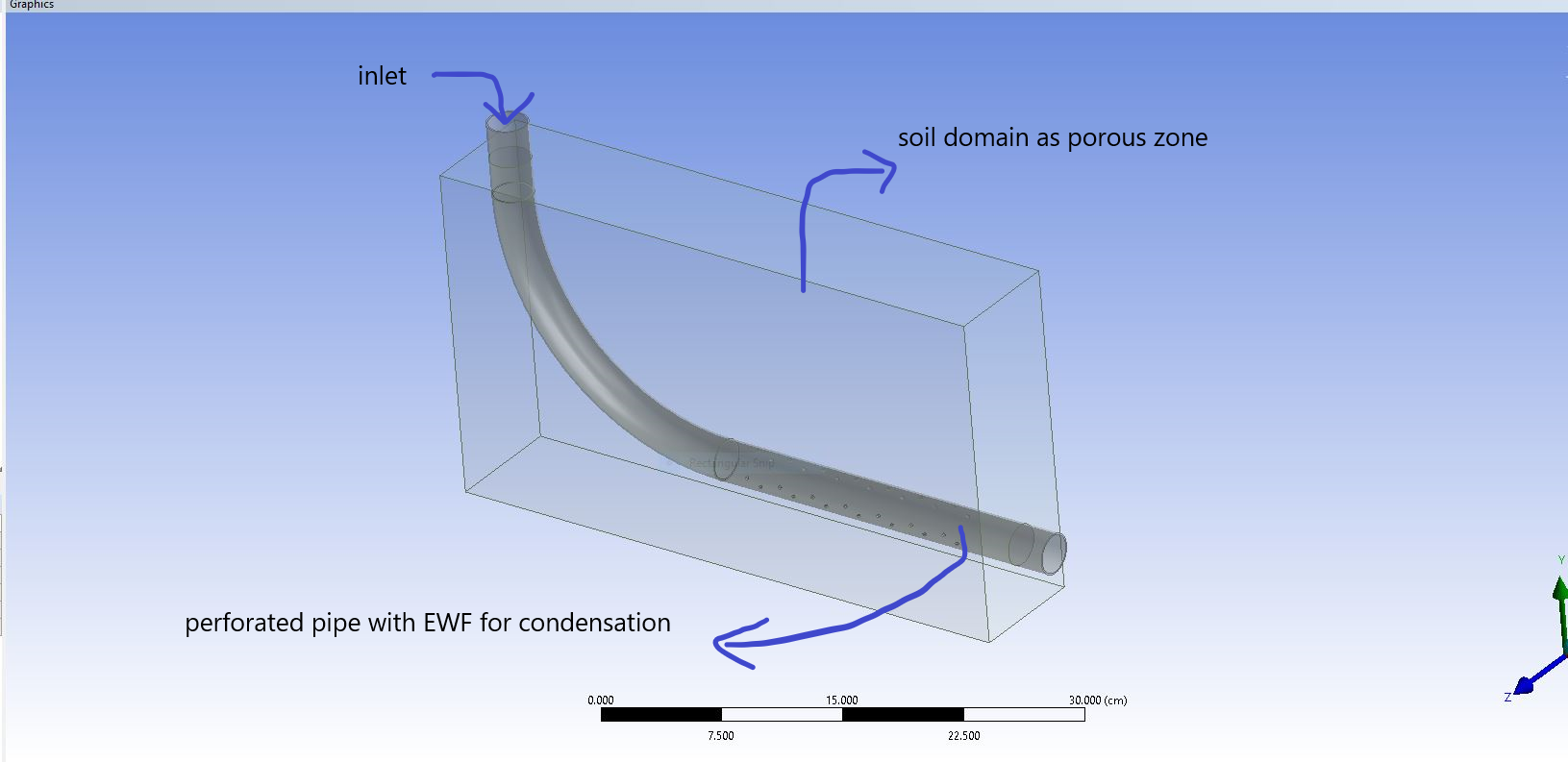
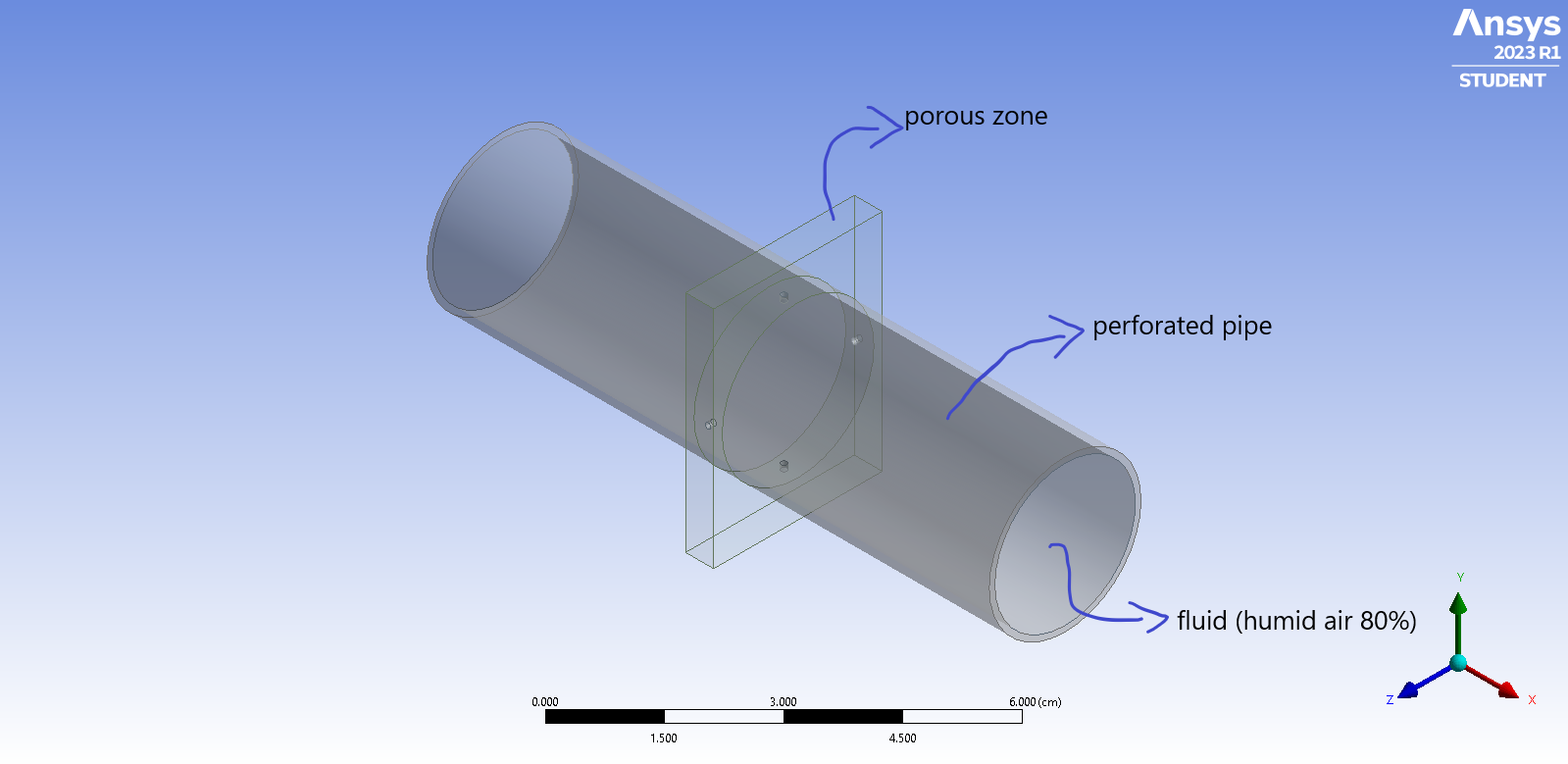
SubscriberYes, there is a perforated pipe burried under soil with EWF on for condensation, soil is modeled as porous zone. I have tried it with 1.2 as growth rate and cell count of 62 millions and it still diverged with the reverse flow at pressure outlet and floating point exception. Fluent was initializing and starting the calculation extremely slow, so I increased the growth rate to reduce the cell count and attached images are for after changing the growth rate from 1.2 to 1.5 and cell count from 62 to 7 millions. I had run the same geometry with diffrent porous coefficients and 0.5 fluid porousity (mentioned above) and reached convergece, but after changing porous coefficients (higher values) and fluid porosity to 0.25, it has been diverging.
-
-
August 8, 2023 at 9:11 am
Rob
Forum ModeratorOK, so humid air flows into the pipe. Condensation occurs (probably very quickly depending on the RH and soil temperature). Where does the condensate go?
-
August 8, 2023 at 4:56 pm
Amir
SubscriberYes condensate (liquid water) forms inside the pipe. Some of it stays inside the pipe and some of it (atleast we expect so) would go into the soil from holes at the bottom of the pipe.
-
August 9, 2023 at 8:09 am
Rob
Forum ModeratorEWF will only track the film on a wall, so how are you transferring from the film to a multiphase model? If you switch off the condensation, how does the RH contour look?
-
August 10, 2023 at 1:50 am
Amir
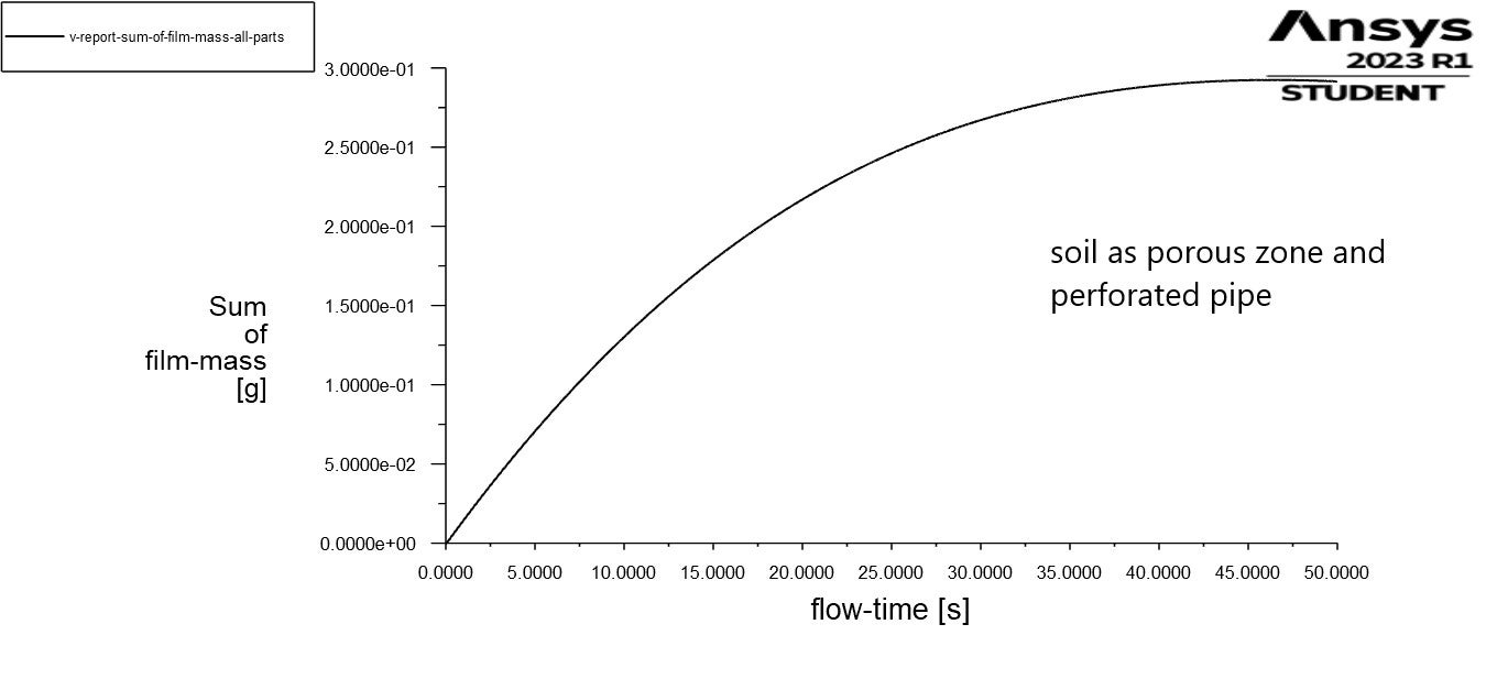
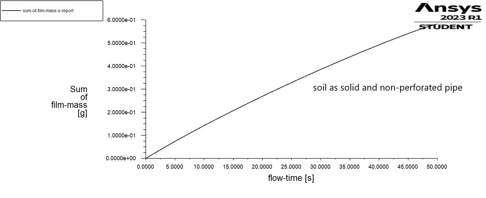
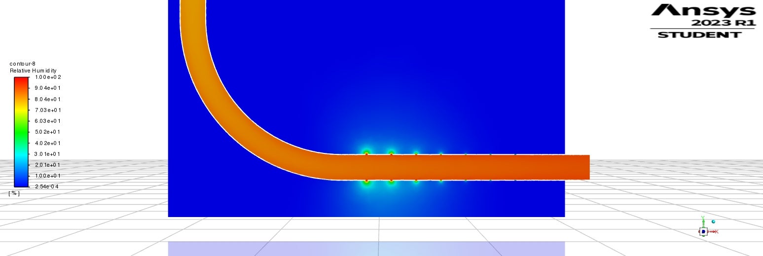
SubscriberWell so far I have been neglecting the part of liquid water that would enter the soil domain, partially because multiphase was off and also comparing two cases: 1-non-perforated pipe with solid soil and 2-perforated pipe with porous soil; there was 0.6g of liquid water in the first and 0.3g in the second [meausred inside the pipe after 50s physical time] so I asumed probably something close to 0.3g liquid water would go into porous soil domain would be negligible. We are mainly concerned about the latent heat exchange during the condensation and not tracking liquid water (please let me know if we made wrong assumption for this).
I am not sure if I understood the second part of your reply, but I am attaching contour of RH for the converged case. EWF was on.
-
August 21, 2023 at 3:12 pm
Amir
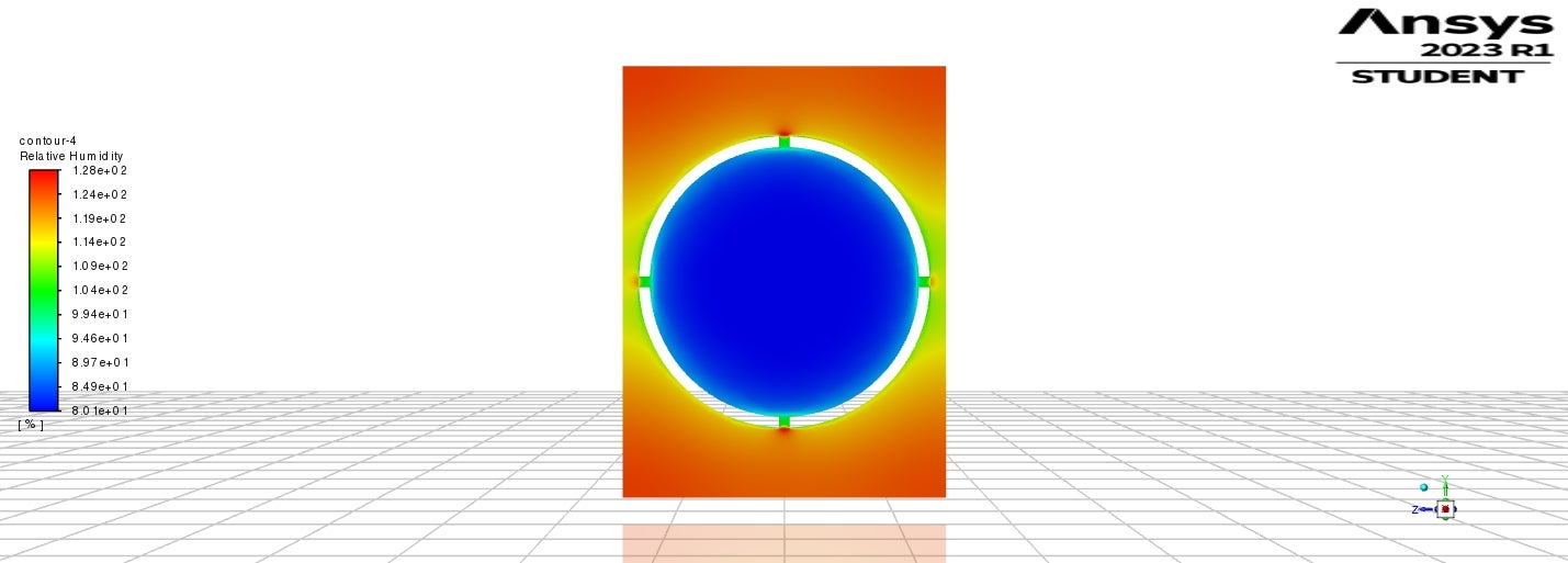
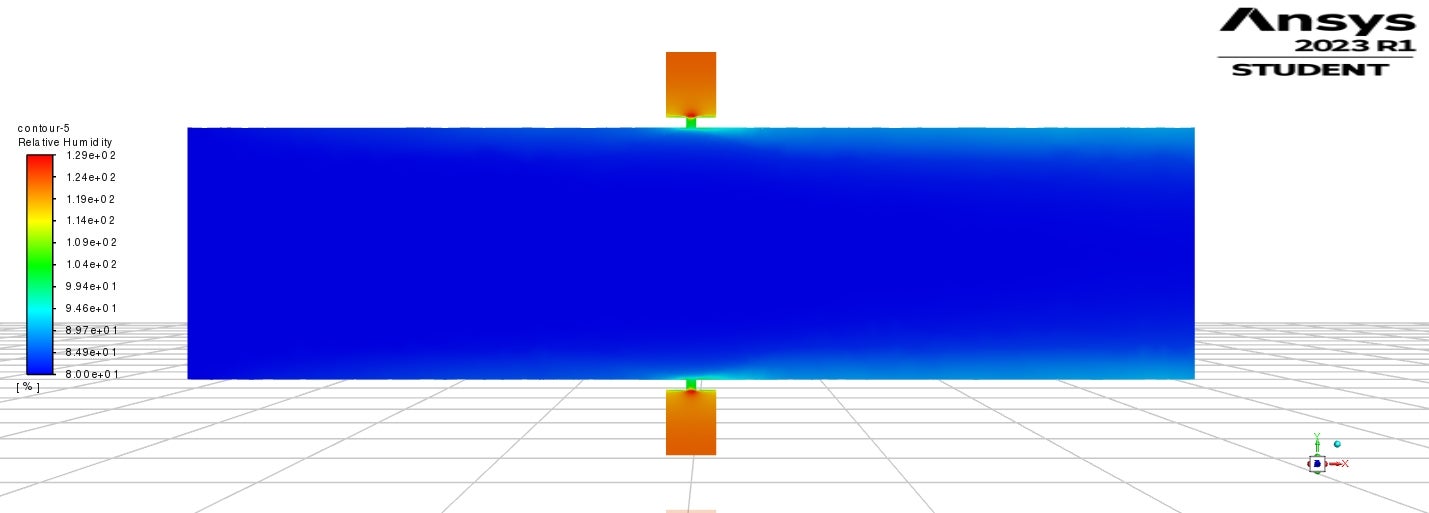
SubscriberRunning the solver without EWF and with non-equilibrium model, the contours of HR shows values above 100% inside the porous zone, that's because in the absence of multiphase model, condensation will not happen and humidity keeps raising, right?
Are the rest of variables results (temperature, pressure,etc) valid?
-
August 21, 2023 at 3:24 pm
Rob
Forum ModeratorThey are valid for your assumptions: you need to consider whether they're good enough to use as engineering data. We often want to know if condensation will be a problem, we may not care how much there is, merely that it might happen. If you need to know how much condensation there is you need to model it.
-
-
-
August 10, 2023 at 7:55 am
Rob
Forum ModeratorIt's an assumption, check the mass conservation to make sure you're happy with that.
-
August 10, 2023 at 4:43 pm
Amir
Subscriberwhich multiphase model would be suitable for this model?
-
-
August 11, 2023 at 7:54 am
Rob
Forum ModeratorGiven it's phase change I'd tend to favour Eulerian - do some reading to see why, and what additional models you'd need.
-
August 12, 2023 at 12:21 am
Amir
SubscriberThanks Rob. When I switch Eulerian multiphase on, the non-equilibrium thermal model for porous zone becomes unavailable. If I set the porous zone conditions first, then turning multiphase on causes fluent to crash.
-
-
August 14, 2023 at 9:51 am
Rob
Forum ModeratorCheck the model compatibility.
-
- The topic ‘Porous zone viscous and inertial resistance coefficients’ is closed to new replies.


-
4833
-
1587
-
1386
-
1242
-
1021

© 2026 Copyright ANSYS, Inc. All rights reserved.

