-
-
March 13, 2025 at 1:52 pm
peter.newman
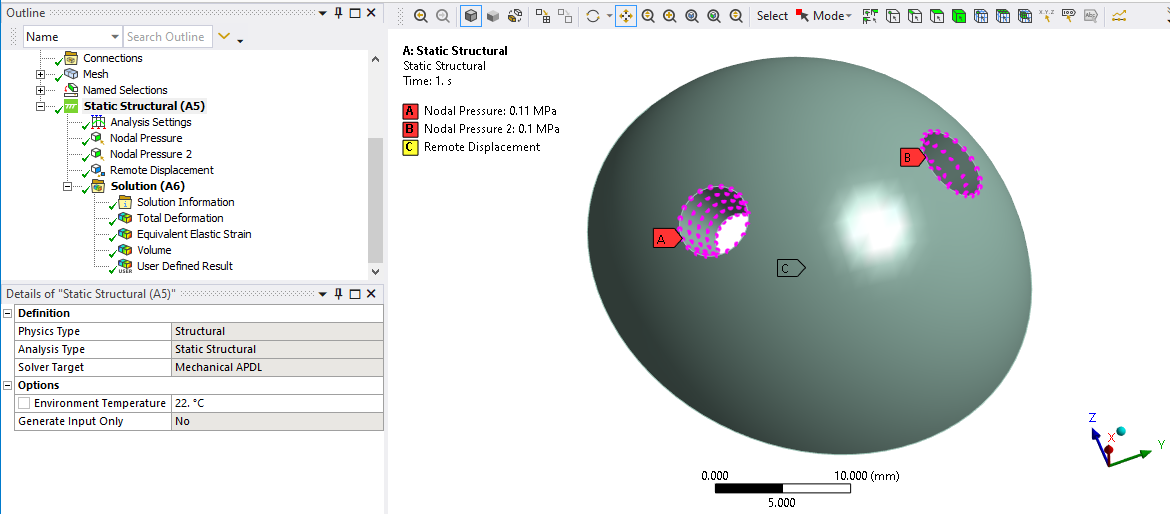
SubscriberI have a 3D model that has a half dome with two holes through the thickness. The hole faces have pressure loads applied, and there is a small pressure difference to induce fluid flow.
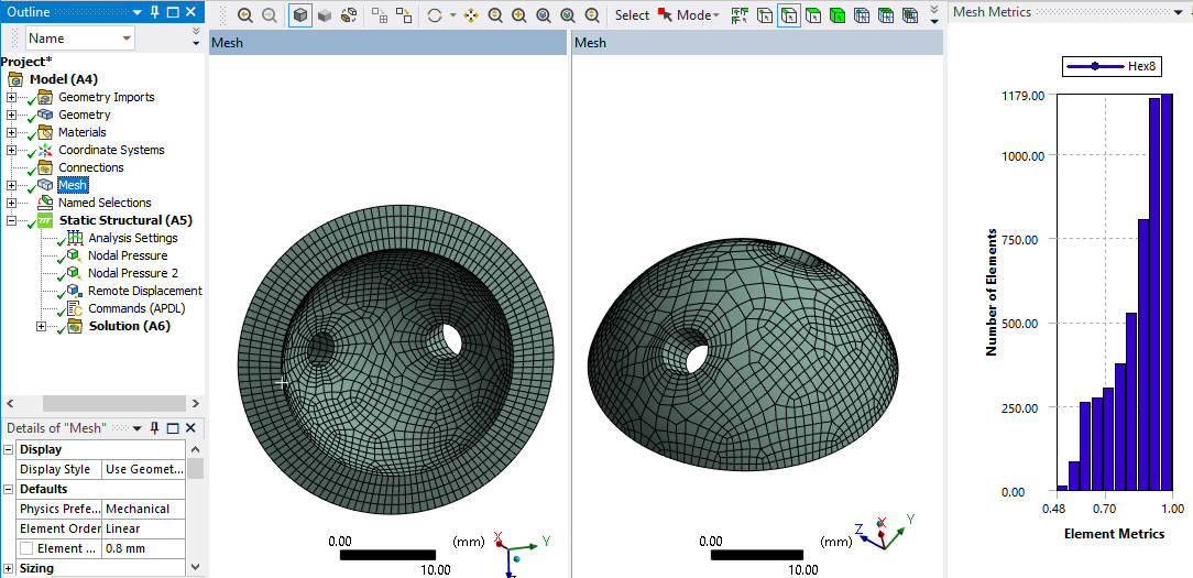
It is meshed with linear hex elements.
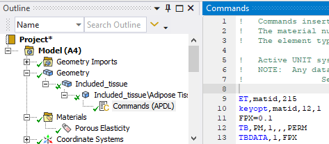
A command object has set the element type to CPT215 and set keyopt(12)=1 to enable the pressure DOF and issued the TB,PM command to set the permeability of the liquid phase.
The material is Porous Elasticity.
Analysis settings has Large Deflection on. It solves and I can see that fluid flow is being computed in the solver output.
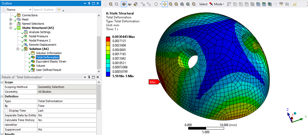
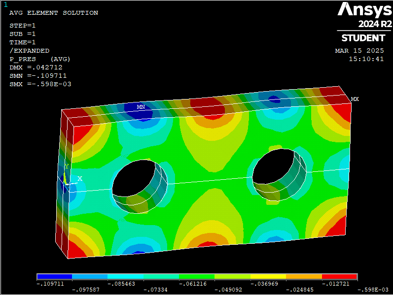
I would like to output the fluid flow through the body and plot the pore pressure in the body. Looking through the worksheet of the available solution quantities, I see an expression for PRES a nodal pressure, but I don't believe that is the Pore Pressure. Please advise how I can obtain the total fluid flow and pore pressure contour.
-
March 13, 2025 at 5:51 pm
dlooman
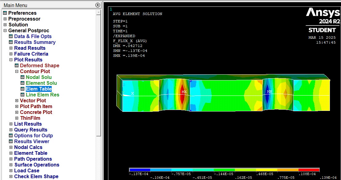
Ansys EmployeeETABLE,p_pres,PMSV,PPRE and ETABLE,f_flux,FFLX,X or Y seem to be the pore pressure and flow flux. FLOW seems to be the "through variable" associated with pore pressure so you may be able to sum the nodal flows with FSUM to get the total flow.
-
March 14, 2025 at 3:58 pm
peteroznewman
SubscriberThanks Dave!
I am a novice at APDL coding and just completed the free course Introduction to Ansys APDL Scripting so I can make progress with the information you provided. I updated the Mechanical model with some named selections for Dome_body, Dome_nodes and Dome_elements to create components and solved the model again. I added a Command object to the Solution branch and tried the following code:
/POST1
SET,LAST,LAST
CMSEL,S,Dome_elements,ELEM
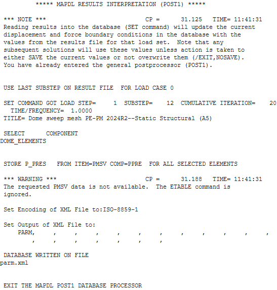
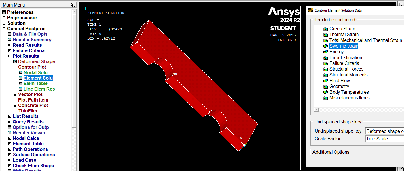
ETABLE,p_pres,PMSV,PPREThe solver output shows the following:
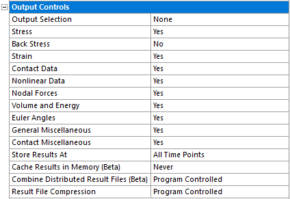
I have turned on every output control I thought it might need.
Do I need to use a *DIM or *GET command?
Please advise.
-
March 14, 2025 at 4:14 pm
dlooman
Ansys EmployeeHi Peter, You answered a lot of structural forum questions in the past. Were you just basing that on the Mechanical gui? What you did should have made the etable results available. Do you want to email me your test? I don't have much experience with the pore pressure elements myself.
-
March 14, 2025 at 5:08 pm
peteroznewman
SubscriberHi Dave,
I’m also new to Pore pressure analysis. This kind of analysis is useful for blood flow through biological tissues and the coupled deformation that the pore pressure causes. I have looked at the Technology Showcase 50 with a 2D example of a slice of brain tissue and want to do a 3D example. I am trying to do it in the Mechanical GUI, but decided to build my skills in MAPDL, so I will come up with a version where the whole model is a MAPDL script such as a rectangular solid with two cylindrical holes. I sent an Ansys2024R2 archive to your email. Thanks for your help with this.Regards,
Peter Newman -
March 15, 2025 at 3:32 pm
peteroznewman
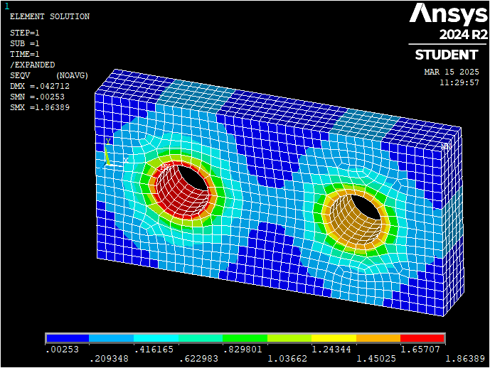
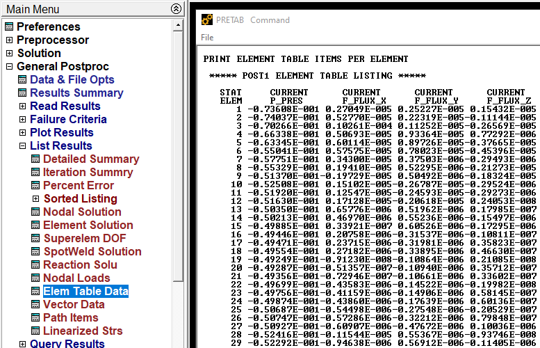
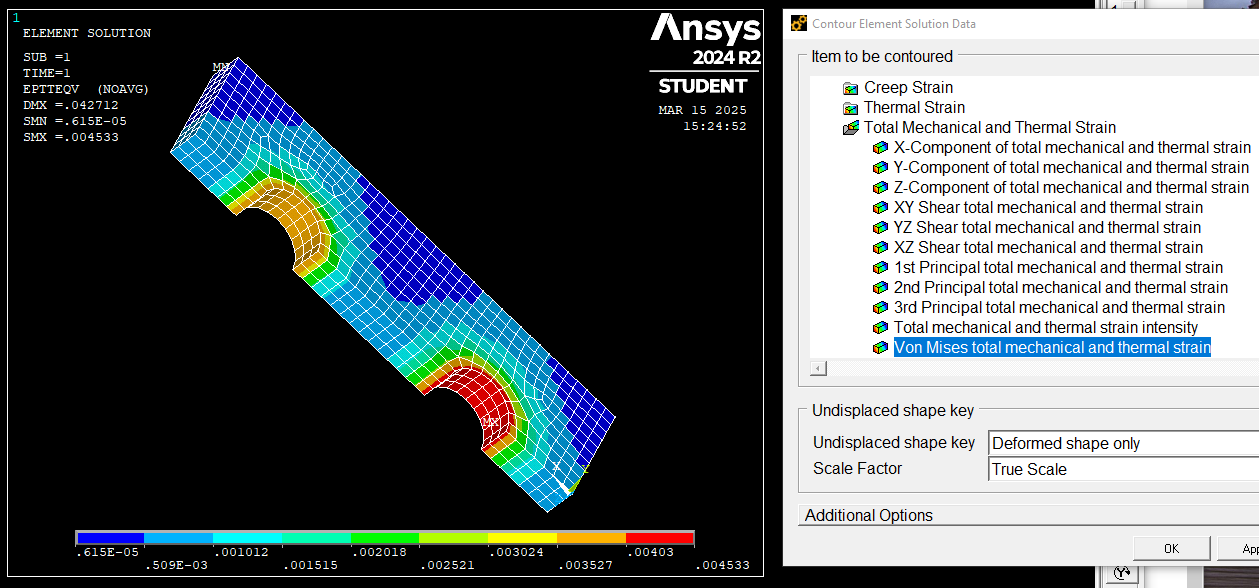
SubscriberI learned a lot about Mechanical APDL in the last 24 hours and wrote a MAPDL script to use the porous elasticity and porous media material on simple quarter symmetry geometry.
finish
/clear
! units of mm kg and N
/prep7
ET,1,CPT215
keyopt,1,12,1
TB,PELAS,1,1,,POISSON
TBDATA,1,0.1,10,0.1,0.45
FPX=0.1e-2
TB,PM,1,,,PERM
TBDATA,1,FPX
ETABLE,p_pres,PMSV,PPRE
! create and mesh geometry
block,,80,,20,,6
cyl4,20,,6,,,,6
cyl4,60,,6,,,,6
vsbv,1,all
VSEL,ALL
MSHAPE,0,3D
ESIZE,2
VSWEEP,4,18
! apply symmetry BCs
nsel,s,loc,y,0
d,all,uy
nsel,s,loc,z,0
d,all,uz
! fix one node in x
nsel,r,loc,y,0
nsel,r,loc,x,0
d,all,ux
! apply pressure loads to areas 9 and 13
pp_inlet=1.1
pp_outlet=1.0
SFA,9,1,PRES,pp_inlet
SFA,13,1,PRES,pp_outlet
allsel,all
finish
/solu
antype,0             ! static analysis
nlgeom,on            ! Turn on Large Deformation
eqsl,sparse,,,,,1
solve
autots,on            ! Turn on auto time stepping
nsub,20,1000,10,OFF
time,1.
finish
/view,1,1,2,3
/expand,2,rect,half,0,-1e-6,0,2,rect,half,0,0,-1e-6
/post1
set,last
plesol,s,eqv
esel,all
ETABLE,p_pres,PMSV,PPRE
ETABLE,f_flux_x,FFLX,X
ETABLE,f_flux_y,FFLX,Y
ETABLE,f_flux_z,FFLX,Z -
March 15, 2025 at 3:48 pm
dlooman
Ansys EmployeeTime well-spent!
-
March 15, 2025 at 5:49 pm
-
March 17, 2025 at 12:53 pm
peteroznewman
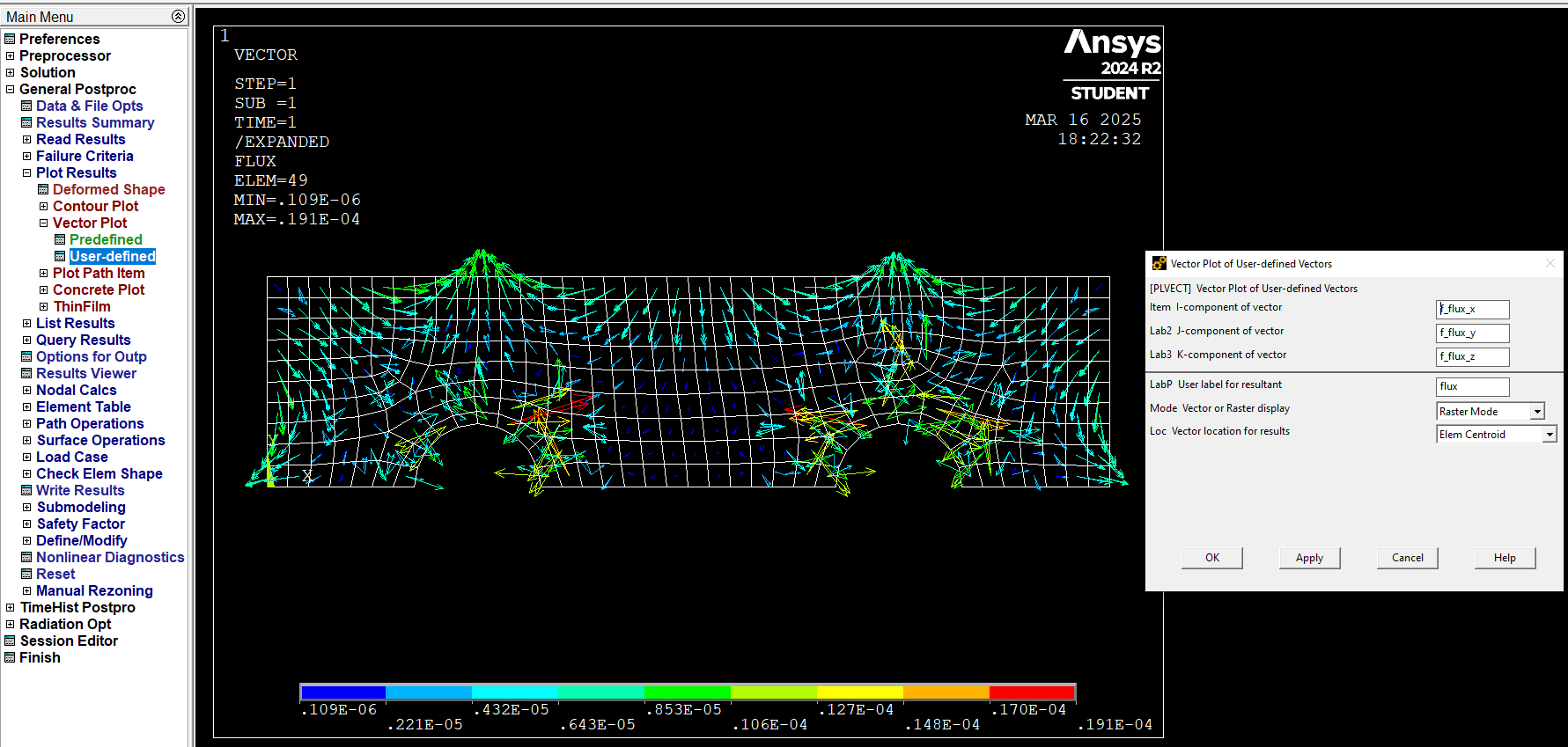
SubscriberThis vector plot of fluid flux answers one question I had about pore pressure analysis. It shows fluid flows into or out of boundary faces that have no boundary conditions applied.
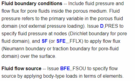
I want flow only through the two faces where a pressure load was applied and no flow through external boundaries. I expect I can prevent fluid leaving an external face by adding a skin of elements of non-porous material to those faces. I wonder if I can do it with boundary conditions instead. Here is what the Ansys Help says in section 2.12 of the Coupled-Field Analysis Guide:
As a quck test, I want to just use faces 4, 5 and 6.
First I tried adding a pressure load of 0 to one face, but that had no effect, I got the same plot as above.
! apply zero pressure load to areas 4, 5 and 6
SFA,4,1,PRES,0
SFA,5,1,PRES,0
SFA,6,1,PRES,0
Next I tried the SF command with the label FFLX. This defines surface loads on nodes. I added the code shown below, but it also had no effect, I got the same plot as above. Please advise.
! apply no flow bc to areas 4, 5 and 6
ASEL,S,AREA,,4,6
CM,Noflow,AREA
NSEL,S,F,FLOW
SF,ALL,FFLX,0 -
March 21, 2025 at 9:14 pm
peteroznewman
SubscriberFollow-on discussion to prevent fluid leaking out the sides of the block is here: https://innovationspace.ansys.com/forum/forums/topic/apdl-code-to-apply-a-skin-of-shell181-elements-on-some-areas-of-a-volume-mesh/
-
- You must be logged in to reply to this topic.


-
5149
-
1836
-
1387
-
1248
-
1021

© 2026 Copyright ANSYS, Inc. All rights reserved.

