TAGGED: floquet-ports, metamaterial, polarization, s-parameters
-
-
April 17, 2024 at 3:46 pm
Tenyu Aikawa
SubscriberHi ANSYS community, I want to do a polarization parameter sweep and an angle of incidence parameter sweep for my metasurface using floquet ports. I know that if you open up the properties window for you floquet port and go to the "mode setup" you can use the "mode calculator" which gives you the option to do an angle sweep for the angle Phi and Theta angles. This seems to be pretty straight forward if I just input my desired angle sweep and step size. However I want to view how each increment of angle sweep will effect the S-parameters of my metasurface.
Usually I can create a project variable and do a parametric sweep of that varible, and I can view that parametric sweep in my S-paramters. But here they give you the option of using a step size. So when I run a simulation with the complete angle sweep that I defined in the "mode calculator" I still get the same results as if I never did a parameter sweep of the angle. When viewing the S-paramters you will only get a single simulation result, instead of multiple simulations for each angle.
Are there certian plots that allow you to view this parameter sweep that you do in the "mode calculator"?
-
April 17, 2024 at 7:28 pm
kaleor
SubscriberHello,
That's a good question. I think the mode calculator just helps you specify which Floquet modes (m,n=[(0,0), (0,1), ...]) you want to include in your simulation. Each mode can be propagating or evanescent, depending on the size of the unit cell. The mode calculator shows which are which so that you can include all the propagating ones and give enough distance for the evanescent ones to disappear before making it to a floquet port. It does not set up the simulation for a parametric sweep over the angles.
You need to define global variables like "$scan_theta" and "$scan_phi" (but any name will do) to do a sweep over different incidence angles. The global varaiables you define go into the phase delay fields for the primary/secondary or lattice pair boundaries. Then you can set up a parameteric sweep for those global variables, and that may give you what you are looking for. The polarization sweep will be built-in to the simulation, where TE and TM modes are the different polarizations (horizontal and vertical).
Best of luck
-
April 18, 2024 at 12:49 am
Tenyu Aikawa
SubscriberThanks for the response, I guess I was thinking of the polarization in the sense of, if I rotated the TE mode around my metamaterial but in that case I would actually be doing a Theta-scan 0-360 degrees (assuming polar coordinates). Then also by doing a Phi-scan I could also control the angle of incidence along the z-axis from 0-90 degrees. So if I understand you correctly, we are actually changing the angle of incidence through the phase delay of the lattice pair boundaries instead of manipulating the floquet ports is that correct?
-
-
April 18, 2024 at 9:06 pm
kaleor
SubscriberYes, that is my understanding: you control the angle of incidence with the phase delay.
-
October 21, 2024 at 10:36 am
rameshvarmapotti
SubscriberHi, I have similar doubt.we can control the angle of incidence with the phase delay. However how to sweep the polarization angle in parametric analysis?
-
October 21, 2024 at 7:11 pm
kaleor
SubscriberIf I understand correctly, you would like to change the polarization oritentation angle \psi, correct (see wikipedia polarization)? If you use a Floquet port excitation, then I believe that the TE and TM modes are essentially horizontal and vertical polarizations. You may need to manually combine those responses to get the response from an arbitrary polarization orientation angle. You could use a plane wave excitation, which may make specifying the polarization angle a bit easier. Getting the boundaries right for that may be a little tricky, though.
-
October 24, 2024 at 5:53 am
rameshvarmapotti
SubscriberThanks for the response, I varied the plane wave excitation. However, Polarization angle given like variable (any name), it cannot be function of intrinsic variable. How will rectify the error?
-
October 24, 2024 at 5:54 pm
kaleor
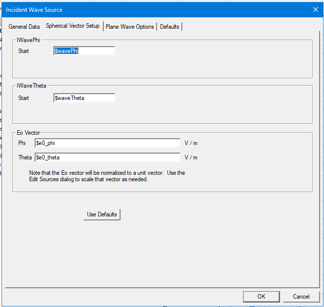
SubscriberI think I understand what you are saying. Let me know if this is incorrect. You have the Eo polarization vector for the plane wave defined with two global variables, say $e0_phi and $e0_theta (see picture below). You have also defined $e0_phi = cos(\psi), $e0_theta = etc., or something like that. I think that would give you the error that you referenced. The only workaround that I can think of would be to run a parametric sweep that simultaneously changes the values $e0_phi and $e0_theta. It may be tedious to enter each pair of values depending on how may \psi angles you would like to do. You could use the pyaedt Python library to programmatically add each set of values.
-
- The topic ‘Polarization and Angle of Incidence Scan with Floquet ports in ANSYS HFSS’ is closed to new replies.


-
4954
-
1639
-
1386
-
1242
-
1021

© 2026 Copyright ANSYS, Inc. All rights reserved.


